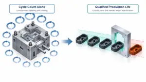
Injection molding cycle time directly affects machine capacity, unit cost, and delivery performance. The correct target is not the shortest possible cycle, but the shortest repeatable cycle that still meets dimensional, cosmetic, and functional requirements in every cavity.
What Is Injection Molding Cycle Time
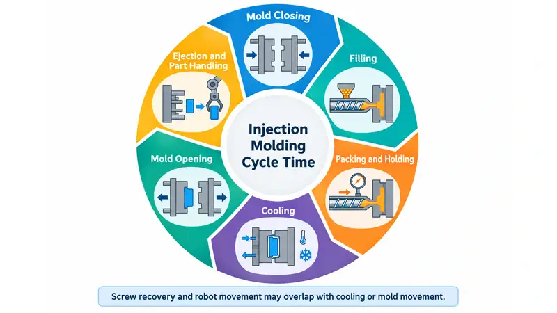
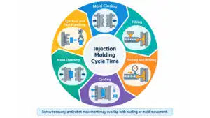
Injection molding cycle time is the time required to complete one molding cycle and begin the next. It normally includes mold closing, filling, packing and holding, cooling, mold opening, ejection, and part handling. Some activities, such as screw recovery and robot movement, may overlap with cooling or mold movement.
| Cycle stage | Typical purpose | Common opportunity |
| Mold closing | Prepare the tool for injection | Improve machine settings and mold alignment |
| Filling | Deliver molten resin into the cavity | Optimize flow path, gate design, and injection profile |
| Packing/holding | Compensate for material shrinkage | Set only the time and pressure the part requires |
| Cooling | Solidify the part for ejection | Improve cooling channels, water flow, and part design |
| Mold opening | Separate cavity and core | Reduce unnecessary open distance |
| Ejection and handling | Remove and transfer the part | Improve ejection, automation, and downstream layout |
How to Reduce Injection Molding Cycle Time
Cycle-time reduction should begin with the stage that actually limits the machine. Record a series of stable cycles and separate filling, holding, cooling, screw recovery, mold movement, ejection, and handling. The average time identifies the largest opportunity; variation reveals delays caused by unstable processing, sticking parts, inconsistent recovery, or manual intervention.
1. Reduce cooling time through better heat removal
Cooling is commonly the largest part of the cycle. The goal is to eject as soon as the part has enough stiffness to retain its shape, not simply to lower the cooling timer. If the mold opens too early, the apparent time saving may be lost through warpage, dimensional drift, or damaged parts.
Wall thickness is usually the strongest design influence. In simplified cooling models, cooling time increases roughly with the square of the controlling wall thickness. A heavy boss, corner, runner, or rib can therefore set the cycle for the entire shot. More uniform walls, cored-out heavy sections, correctly proportioned ribs, smooth transitions, and adequate draft can reduce cooling and improve part quality at the same time.
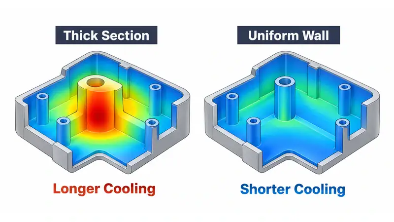
The cooling system should remove heat uniformly rather than merely use colder water. Check coolant flow, inlet and outlet temperatures, pressure drop, mold-surface temperature, and local hot spots. Scale, restrictive fittings, unequal parallel circuits, and channels located too far from the cavity reduce heat transfer. Baffles, bubblers, separate circuits, high-conductivity inserts, or conformal cooling may help where straight drilled channels cannot follow the geometry. Thermal simulation is useful when it includes the actual channel layout, coolant conditions, mold materials, and resin data.
2. Optimize filling instead of using maximum speed
A shorter filling time is useful only if the flow front remains balanced and repeatable. Excessive speed can increase shear heating, trap gas, create burns or jetting, and raise pressure at the parting line. Low speed can cause hesitation, flow marks, premature freezing, or short shots.
A staged injection profile often works better than one maximum speed. Use the speed required through the gate and stable flow sections, then slow the flow where air must escape or where cosmetic features are sensitive. Confirm runner balance, venting, gate capacity, peak pressure, and cavity-to-cavity part weight before accepting the faster profile.
3. Set packing and holding time from gate seal
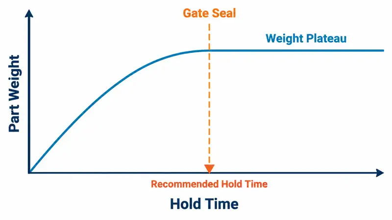
Holding pressure compensates for shrinkage only while the gate remains open. After the gate seals, additional hold time no longer adds material to the cavity and only extends the cycle. A gate-seal study provides a practical endpoint: keep the other settings constant, increase hold time in small steps, and weigh parts from each cavity after a consistent conditioning period. When part weight reaches a repeatable plateau, add a small process margin and confirm dimensions, sink, voids, appearance, and ejection.
Packing pressure also needs a stable window. Too little can leave sink, voids, or undersized features; too much can cause flash, residual stress, and difficult release. Gate size affects both packing and cycle time. A small gate freezes quickly but may require high shear and pressure, while a larger gate can improve packing but increase gate vestige and seal time.
4. Keep screw recovery inside the cooling window
Screw recovery normally occurs while the part cools, so it does not extend the cycle unless dosing finishes late or varies from shot to shot. If recovery is the bottleneck, review machine plasticizing capacity, shot utilization, screw speed, back pressure, barrel profile, and material feed condition. Stay within the resin supplier’s processing guidance. Excessive screw speed or back pressure can raise melt temperature, degrade sensitive materials, shorten reinforcing fibers, and make dosing less stable.
5. Shorten mold movement ejection and handling
Use only the mold-open distance required for the part, runner, robot tooling, and any slide or core movement. Controlled acceleration and deceleration can reduce motion time without creating impact or mold-protection problems. When a part needs repeated ejector strokes or manual assistance, correct the release problem instead of increasing ejector speed. Typical causes include insufficient draft, vacuum on the core, unsuitable texture direction, uneven shrinkage, or poorly distributed ejector force.
Automation is most valuable when handling limits the cycle or creates quality and safety risks. Coordinate the robot path, gripper, ejector sequence, mold-open distance, and downstream placement as one motion plan. A faster robot provides little benefit if it waits for excessive mold travel or an unreliable ejection sequence.
6. Maintain and validate the improved process
A validated cycle can drift as cooling passages scale, vents clog, gates wear, ejectors bind, or slides lose alignment. Track coolant flow, vent condition, gate and parting-line wear, moving components, dryer performance, and sensor repeatability. Preventive maintenance protects both cycle time and the quality window.
After each change, allow the process to return to steady state and confirm results across all cavities. The validation should include cycle average and variation, part weight, critical dimensions after the specified conditioning period, appearance, function, yield, alarms, downtime, and manual intervention. A shorter machine cycle is not a real improvement if scrap or downstream correction increases.
Reduce Cycle Time with Moldie Through Practical Tooling Engineering
At Moldie, we approach cycle-time reduction through the combined effect of part design, mold cooling, runner and gate design, ejection, and production handling. We focus on finding the real limitation in the molding cycle, then improving it without compromising part quality or tool reliability.
For injection molding projects with defined volume, resin, and quality requirements, contact us to review the tooling approach early and help build a more stable, efficient production process.