Flow marks on a molded housing, trim panel or industrial component can lead to sorting, rejected shipments and repeated mold trials. For OEM buyers and quality teams, the goal is an acceptable surface produced consistently at the agreed cycle time. A single clean sample is not enough to release a process for repeat orders.
Start by confirming the defect, then investigate material condition, actual temperatures and filling behavior before changing the tool. This guide explains how to separate a process issue from a gate, cooling or part-design limitation and what evidence to request before approving a corrective action.
What flow marks look like
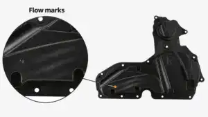
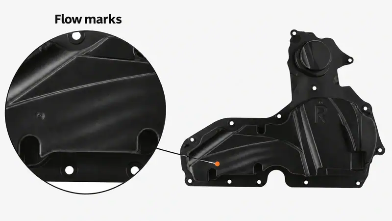
Flow marks are visible bands, ripples or gloss variations associated with melt movement and surface formation. Cold material, hesitation and premature skin freezing can leave a pattern as the cavity fills. Record-groove marks often run across the local flow direction; near a gate, they may appear as concentric rings. A line does not have to run along the flow direction to be a flow mark.
Appearance alone cannot establish the cause. Note where the mark starts relative to the gate, whether it repeats at a thickness change, and whether it affects every cavity. A cosmetic band is not automatically a structural defect, but a visually similar weld line or degraded material may require separate functional investigation.
Separate flow marks from similar defects
| Observed pattern | Possible defect | First distinction to investigate |
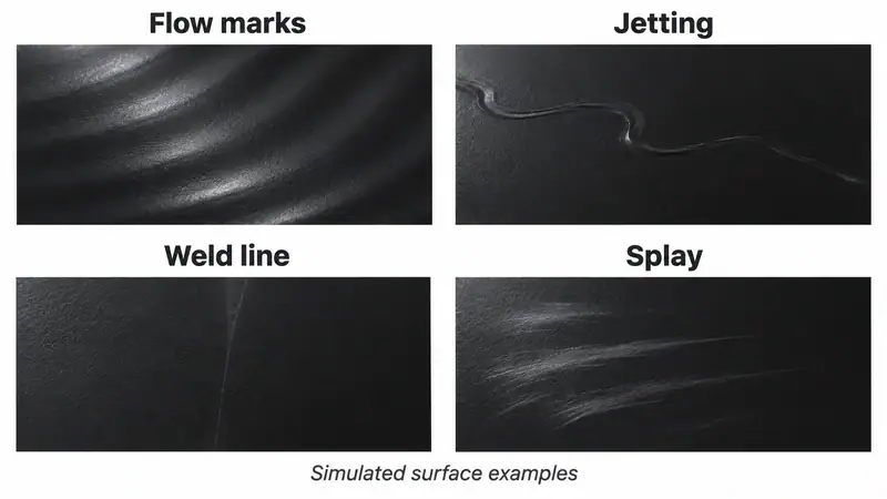
| Repeated ripples or gloss bands | Flow marks or record grooves | Cooling and velocity of the advancing front |
| Snake-like strand from the gate | Jetting | Melt entering an open space without guided wall contact |
| Seam where fronts meet | Weld line | Flow around a hole, insert or multiple gates |
| Feathered silver streaks | Splay | Moisture, gas, contamination or degradation |
| Brown or black end-of-fill area | Burn mark | Trapped gas and local overheating |
| Alternating gloss bands on some blends | Tiger lines | Material-specific flow instability |
These observations guide investigation; they are not diagnoses from a photograph. In particular, tiger lines and filled-resin surface streaks may need input from the resin supplier. Applying the same temperature change to every kind of banding can hide the actual problem.
Define the appearance requirement before trials
Identify the surfaces that matter to the end product and agree on lighting, viewing distance, viewing angle and inspection time. Use approved reference samples or limit samples to define acceptable appearance. A defect that is obvious on a glossy front panel may have a different acceptance limit on a concealed bracket.
For an existing nonconformance, keep cavity identification and lot traceability and agree on containment for affected stock. Record the defect rate using consistent inspection conditions. This gives purchasing and quality teams a baseline for judging the correction and estimating its effect on delivery.
Use location and timing to narrow the investigation
| When or where it appears | Check first | Evidence to request |
| Near the gate or after a restart | Cold material, nozzle condition and entry velocity | Restart samples and early filling progression |
| After a rib or wall transition | Hesitation or an abrupt velocity change | Short-shot sequence linked to part geometry |
| Toward the end of the flow path | Heat loss, pressure restriction and venting | Fill time, pressure trace and vent condition |
| In one cavity only | Local gate, cooling or runner imbalance | Cavity-specific samples and temperature checks |
| After a material or color change | Resin preparation and additive dispersion | Lot records, drying records and purge history |

A controlled sequence for reducing flow marks
1. Establish a stable material and machine baseline
Confirm the resin grade, colorant, approved regrind proportion and any recent lot changes. Follow grade-specific drying and handling requirements; verify moisture where the material requires it. Drying may resolve moisture-related splay, but it is not a general cure for a frozen flow front.
Allow the machine and mold to reach stable production conditions. Save the current recipe and record actual fill time, injection pressure, transfer position, cushion, part weight and cycle time. Keep labeled samples from each cavity. If shot delivery varies, investigate that instability before comparing cosmetic changes.
2. Verify actual mold and melt temperatures
A cold mold surface or viscous melt can contribute to premature freezing. Check cooling-circuit flow, blocked passages, local inserts and actual thermal conditions rather than relying only on controller setpoints. A repeatable mark in one area may point to a local temperature difference.
Where evidence supports a thermal cause, trial a controlled temperature change within the resin supplier’s processing range. Allow the mold to stabilize before collecting samples. Track sticking, dimensions and cycle time as well as appearance. Excessive melt temperature or residence time can introduce degradation and new streaks.
3. Relate the defect to the filling profile
Use an appropriate short-shot study to observe the advancing front and identify hesitation near the affected feature. Compare the commanded injection speed with actual velocity and pressure. If the machine reaches its pressure limit, the front may slow even when the programmed speed is high.
A front that cools during slow filling may benefit from higher velocity through the affected region. Jetting at the gate may need a gentler initial stage, followed by faster filling once the melt is guided by the cavity wall. Keep transitions smooth and check for flash, gate blush and burns. There is no universal speed increase for every surface mark.
4. Check transfer and packing after filling is stable
An early velocity-to-pressure transfer can slow the front before filling is complete. Review the transfer position and pressure response alongside cushion stability. Packing can improve surface replication in some conditions, but additional hold pressure cannot reliably erase a pattern already formed during unstable filling.
For a gate that seals by freezing, compare part weight as hold time increases to help identify effective gate seal. Extending hold after the gate seals adds cycle time without feeding the cavity. For valve gates, review closure timing and packing access. Check dimensions and stress-related behavior before accepting a higher packing setting.
5. Inspect cold slug control and the flow path
If marks begin with the first material entering the cavity, inspect nozzle behavior, cold-slug wells and runner dead areas. A restrictive gate or runner can create excessive pressure loss or unfavorable entry conditions. Check vents where the last regions fill; their condition matters when trapped gas interferes with filling.
Use one-variable trials to establish the main effects, recording both improvements and new defects. If interactions between settings remain unclear, use a planned experiment with the process engineer. Retain the best stable baseline so further tests do not lose a reproducible reference.
When a tooling or part change is justified
Escalate to a design review when acceptable appearance requires temperatures outside the approved range, excessive pressure, an uneconomic cycle or settings that repeatedly create other defects. Revisit gate size, gate type and location, runner restriction, cold-slug capture and cooling balance. Review abrupt wall transitions and flow around bosses or inserts with the part designer.
Request a documented comparison of proposed changes, their expected effect and their implications for gate marks, dimensions and cost. Filling simulation can help compare locations and flow patterns, but trial parts must confirm the surface result. Polishing, texturing or painting should be reviewed against the appearance specification after the molding cause has been assessed.
Evidence to request before closing the issue
Approve the correction against the original appearance requirement and the production conditions. Agree on a representative validation run based on program risk and customer requirements. Check all relevant cavities and include restart or shift-change conditions where those triggered the defect.
- Before-and-after samples and photographs taken under the same inspection conditions.
- A trial record showing the changed variables, actual process response, defect rate and final cycle time.
- Dimensional and functional results after the specified conditioning period, including affected assembly or sealing features.
- The approved recipe and operating limits, material preparation requirements and maintenance actions needed to sustain the result.
- An inspection and reaction plan defining what to do if the mark returns.
A successful correction delivers acceptable appearance without exchanging it for warpage, flash, stress or an impractical cycle. Monitor the agreed visual reject rate separately from capability results for measurable dimensions; one does not establish the other.
Discuss surface quality with Moldie before production
Moldie’s project workflow includes DFM and simulation, mold manufacture, sampling and validation. For a new project, share part files, resin grade and color, forecast volume, surface finish and cosmetic acceptance criteria. For an existing flow-mark issue, add cavity-labeled samples, defect photos, the current process record and a history of attempted corrections.
These inputs allow the discussion to focus on whether the next step is a controlled process trial, tool maintenance or a design change, with clear acceptance requirements for the next samples. Contact Moldie about your molding project.