Sink marks can make an otherwise usable plastic part fail cosmetic inspection. Resolving them requires matching the remedy to the cause. A brief look at how they form helps explain which process or design change to try first.
What are sink marks
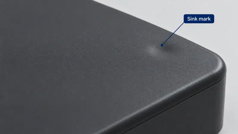
Sink marks are shallow depressions on the surface of injection-molded parts, commonly opposite ribs, screw bosses and thick wall sections. They can be especially visible on glossy or dark surfaces. Unlike an internal void, a sink mark changes the outer surface profile; its acceptability depends on the product’s appearance requirements.
What causes sink marks
The outer skin of a molded part begins solidifying while thicker internal regions remain hot. As those regions cool and contract, insufficient packing compensation can allow the surface to pull inward. Excessive local thickness, inadequate hold pressure or time, early gate freeze and uneven cooling can all contribute. Resin shrinkage behavior also affects the risk.
The practical response is to improve packing, balance cooling or reduce excess material. For an existing tool, begin with controlled process adjustments. For a new part, address geometry before tooling. The seven methods below explain what to change and how to check the result.
Where sink marks usually appear
- On the cosmetic face opposite a rib, boss, snap feature or internal corner.
- At heavy wall sections or where wall thickness changes suddenly.
- In thick areas far from the gate, especially when the gate freezes before packing is complete.
- At locations with limited or uneven cooling around inserts, columns or dense internal geometry.
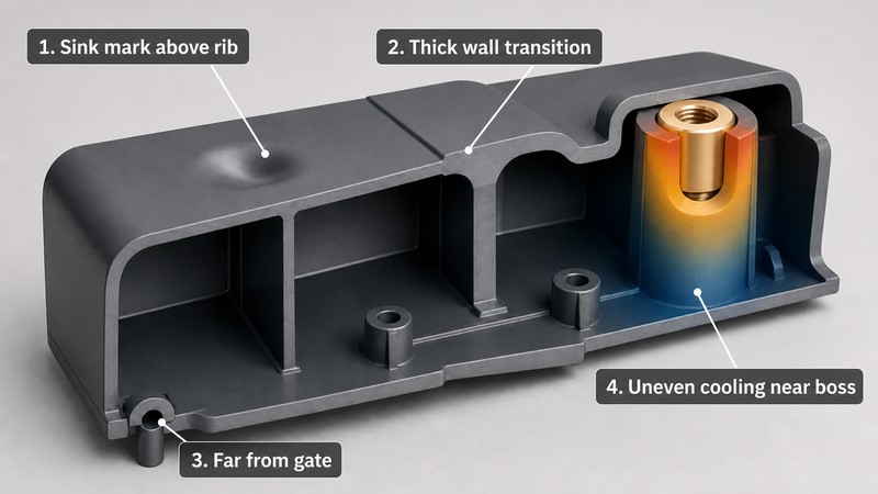
How to Reduce and Fix Sink Marks
1.Increase hold pressure to compensate for shrinkage
First establish a repeatable baseline with stable fill time, material preparation and screw cushion. Mark the affected area and identify the cavity. If shot delivery varies from cycle to cycle, correct that instability before comparing pressure settings; otherwise, a temporary appearance improvement may be mistaken for an effective adjustment.
If the cavity is underpacked, raise the hold or packing pressure in small, controlled steps while keeping other settings stable. This can push additional material into the cavity as the plastic contracts, provided the gate and feed path remain open. Allow the process to stabilize at each setting, then compare several parts for sink depth, weight and dimensions.
Use the lowest pressure range that consistently meets the requirements. Stop increasing pressure if it causes flash, difficult ejection, excessive dimensional growth or other signs of overpacking. A cosmetic improvement that creates another defect is not a production solution.
If sink marks barely respond to higher hold pressure, check whether the gate has already frozen or a narrow feed path is restricting pressure transmission. Raising the machine setting cannot reliably compensate for a section that is isolated from packing.
2.Extend hold time until packing is effective
Too little hold time can stop material compensation early or allow material to flow back before the gate seals. At a fixed hold pressure, increase hold time in steps and weigh several stabilized samples from each cavity. Keep the thermal cycle consistent so changes in cooling do not obscure the comparison.
For a conventional gate that freezes during the cycle, a repeatable weight plateau can indicate gate seal. Confirm with cavity-pressure measurements where available. Select a hold time that reliably maintains packing through the effective gate-open period, with an appropriate allowance for normal process variation.
Extra hold time after gate seal will not feed more material into the part. If weight stops increasing but the sink remains, move on to cooling, local geometry and gate design. For valve-gated hot runners, review the valve-closing sequence as well.
3.Extend cooling time and correct local hot spots
If the depression becomes more pronounced after ejection, test a longer cooling time. Compare parts after the same interval outside the mold to see whether additional in-mold cooling improves the surface. Record the cycle-time penalty alongside the appearance result.
Also check coolant flow, blocked passages and temperature differences between circuits. Thick bosses, deep cores and inserts may retain heat even when the overall mold temperature appears acceptable. Correct a cooling fault before compensating with a longer cycle.
Compare the original and revised cooling conditions using the same inspection timing and lighting. If the longer cycle offers little improvement, restore the baseline and investigate another cause instead of continuing to add cooling time without evidence.
For persistent hot spots, consider targeted tooling changes such as revised cooling passages or suitable cooling inserts. Evaluate their effect on surrounding areas because uneven heat extraction can create warpage. Longer cooling helps stabilize the part before ejection; it does not replace material missing after packing ends.
4.Balance melt temperature mold temperature and filling
Verify actual melt and mold temperatures against the resin supplier’s recommended range. If excessive heat is prolonging cooling, trial a modest reduction and check the result. Keep enough heat for reliable filling, pressure transmission and the required surface finish.
Avoid lowering temperatures indiscriminately. A colder gate or flow path can freeze earlier and reduce the opportunity to pack a thick section. A setting that reduces surface sinking but introduces short shots, poor replication or internal voids needs further investigation.
Check filling consistency and velocity-to-pressure transfer too. Early transfer can leave the cavity underpacked, while late transfer may produce pressure spikes. Adjust injection speed only for a clear filling problem: neither faster nor slower injection is a universal sink-mark remedy. Retest hold conditions after changes that affect gate behavior.
5.Reduce thick walls ribs and boss roots
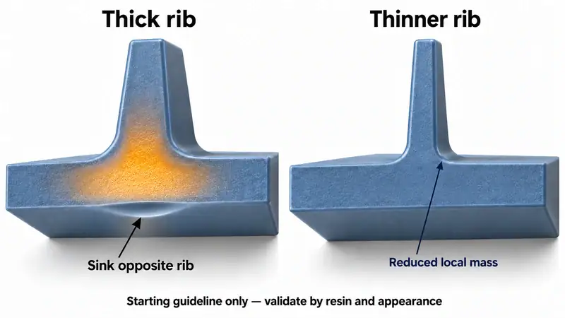
When the mark consistently appears opposite a heavy feature, reduce the local material buildup. Core out solid sections, use ribs for stiffness and replace abrupt thickness changes with gradual transitions. Examine intersecting ribs and boss roots together, since several individually acceptable features can create one oversized junction.
As an initial guideline, rib bases are often about 40% to 60% of the adjoining nominal wall thickness. For a 2.5 mm wall, that suggests roughly 1.0 to 1.5 mm before material-specific validation. Check strength, draft, filling and cosmetic requirements rather than applying the ratio automatically to every feature.
Hollow out heavy bosses where practical and review the supporting ribs and root radii. Keep enough radius to manage stress without adding excessive mass behind the visible face. These changes are easiest before tooling; on an existing mold, confirm the modification route and functional consequences with the toolmaker.
Use a section through the defect location to compare the outer wall with the feature directly behind it. This makes the proposed change concrete: remove the excess section, then verify that the revised feature still supports the required assembly and loading conditions.
6.Improve gate location and the packing path
If a thick area remains underpacked after reasonable process trials, review gate size, location and runner restrictions. A gate that seals too early or feeds through a thin section may prevent pressure from reaching the problem area. A revised gate or less restrictive feed path may improve packing.
Use trial evidence and flow analysis to assess the change before cutting steel. Moving a gate closer to a thick section can help, but may also change weld lines, gate appearance, filling balance and warpage. For multi-cavity molds, compare each cavity separately so a local restriction is not hidden by an average part weight.
7.Review the resin when design and processing remain constrained
Check that trials use the intended production grade, colorant and filler content. Different grades have different shrinkage and flow behavior, so a process developed for one formulation may not suit another.
If material selection is still open, discuss alternatives with the resin supplier and molding partner. Evaluate cosmetic performance alongside strength, chemical resistance, dimensional requirements and cost. A resin change requires renewed validation; lower nominal shrinkage alone does not guarantee a sink-free part.
Confirm the fix before production approval
Change one variable group at a time and retain identified samples. Confirm appearance, dimensions and repeatability across cavities after the agreed conditioning period. Save the successful settings and practical operating range. If improvement requires excessive pressure or cooling time, return to the part and mold design rather than approving a fragile process.
Ask Moldie to review your sink mark problem
Send Moldie your 3D part file, resin grade, cosmetic requirements and photographs of the affected area. For an existing tool, include cavity identification and trial settings. Our team can review wall sections, ribs, bosses, gate strategy and cooling risks to help identify the next practical change. Contact Moldie to start your project.