From consumer products to industrial systems, injection molding is one of the most widely used manufacturing methods for producing plastic parts found in various electronics. The injection molding process converts thermoplastic pellets into precise, repeatable components that protect circuits, route signals, and give devices their physical form.
For product designers, sourcing managers, and engineers, the value of injection molding in the electronics industry comes down to three things: dimensional accuracy at scale, broad material options for electrical and thermal performance, and the ability to integrate multiple functions into a single molded part.
Common Electronics Components Made With Injection Molding
The range of injection molded electronics spans from simple protective covers to highly integrated structural parts.
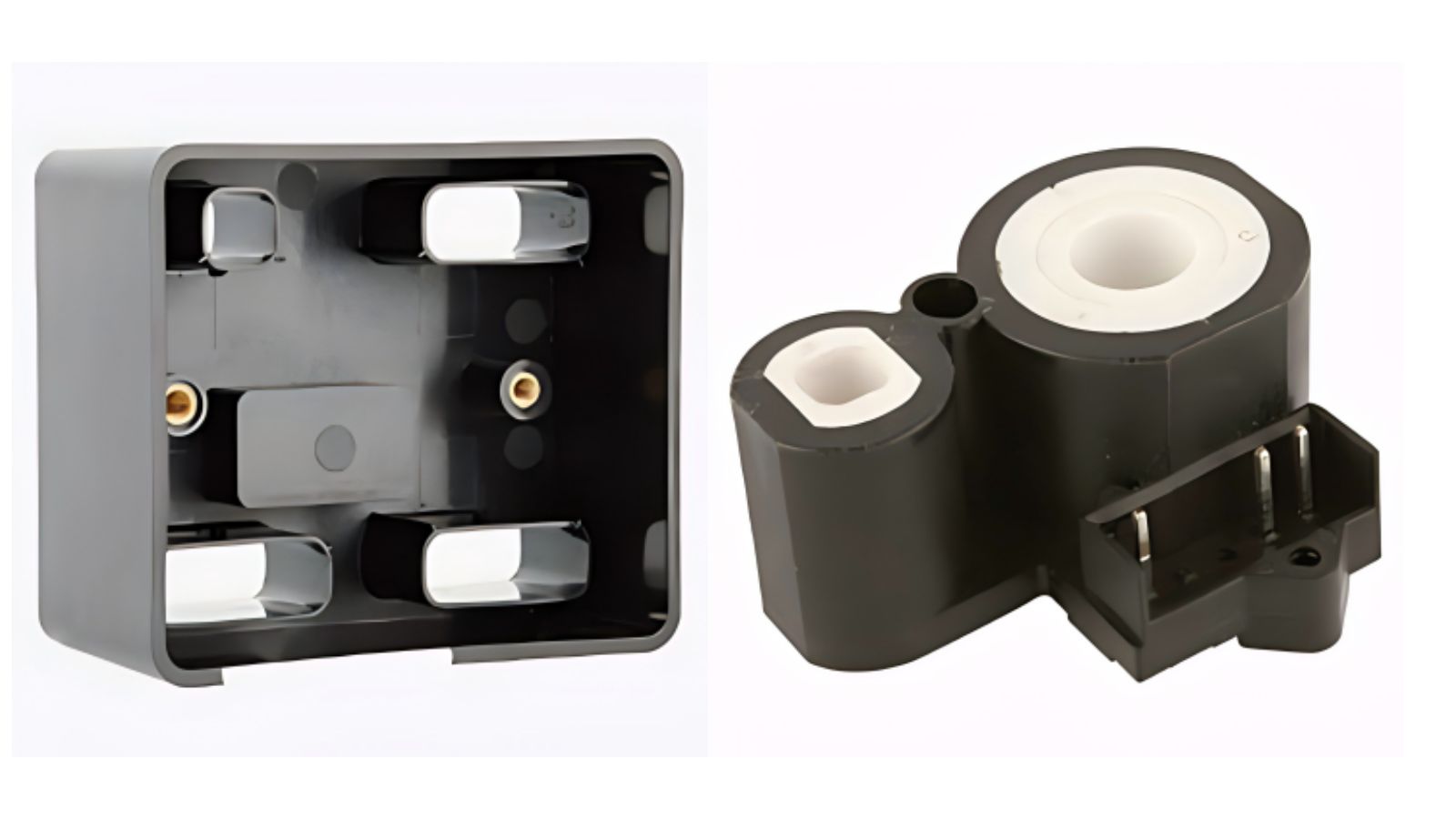
Injection Molding Electronics Enclosure
Electronic enclosures are among the most common injection molded parts. Housings for consumer devices, industrial controllers, and medical monitors all rely on injection molding for consistent wall thickness and precise feature placement.
Design details like boss locations for screws, snap-fit tabs, and alignment ribs are built directly into the mold. This eliminates secondary machining for many assembly features.
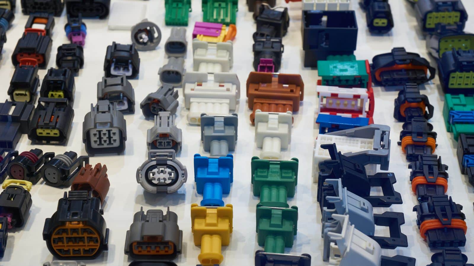
Electrical Connectors and Circuit Board Components
Electrical connectors demand some of the tightest tolerances in electronics molding. For example, a housing off by a few thousandths of an inch may not seat properly on a PCB. What’s more, pin spacing, latch geometry, and housing alignment must be exact to ensure reliable signal and power transfer.
These precise dimensions are maintained through controlled process parameters, including repeatable cavity pressure, melt temperature, and cooling rates.
Connector bodies are often molded from high-performance resins like nylon or liquid crystal polymer (LCP) that withstand soldering temperatures and resist moisture. Insert molding is frequently used to bond metal terminals directly into the plastic during the molding cycle.
Outlet Covers, Switch Plates, and Cable Management Parts
Everyday electrical parts like outlet covers, switch plates, conduit fittings, cable ties, and wire spools are produced in very high volumes through injection molding. These parts require:
- Electrical insulation to prevent shock hazards
- Flame resistance per UL or IEC standards
- Dimensional consistency for fit with standard electrical boxes and hardware
Dashboard switches and knobs in automotive applications also fall into this category, where tactile feel, durability, and appearance all matter.
Material Selection for Electronics Injection Molding
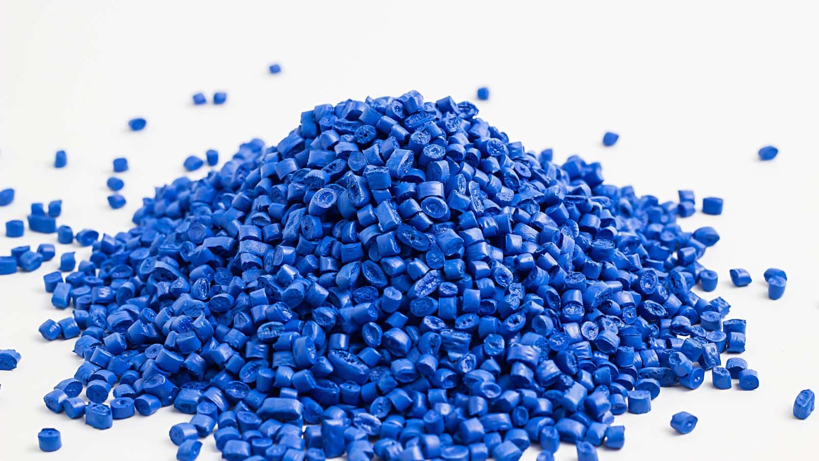
Choosing Resins for Insulation, Heat Resistance, and Durability
Electronic parts face a combination of demands that narrow the field of suitable plastics. The resin must insulate electrically, resist the heat generated by circuits or soldering, and hold up to repeated mechanical stress such as plugging and unplugging connectors.
Key properties to evaluate include:
| Property | Why It Matters |
|---|---|
| Dielectric strength | Prevents electrical breakdown between conductors |
| Heat deflection temperature | Determines performance near heat sources |
| UL 94 flame rating | Required for many electrical and electronic applications |
| Moisture absorption | Affects dimensional stability and insulation over time |
| Impact resistance | Protects against drops and mechanical loads |
Polycarbonate, Nylon, and Polyamide in Electronics Applications
Polycarbonate (PC) is widely used for transparent or translucent parts like LED covers and display windows. It offers high impact resistance and good thermal stability.
Nylon (polyamide, PA) is a go-to material for connectors and structural components. PA 6/6 provides excellent strength, wear resistance, and tolerance for elevated temperatures near solder joints.
Other resins commonly used in electronics include ABS for device housings, PBT for connectors, and PC-ABS blends that balance toughness with processability.
Balancing Design Flexibility With End-Use Performance
Design flexibility is one of injection molding’s strengths. Engineers can incorporate thin walls, living hinges, internal ribs, and complex surface textures. The challenge is ensuring that the chosen resin supports all these features without compromising end-use performance.
For example, a thin-walled enclosure molded in a brittle material may crack during drop tests. A connector housing in a resin with high shrinkage may lose dimensional accuracy. Early DFM review and mold flow analysis help identify these conflicts before tooling begins.
Advanced Processes for Functional Electronic Parts
Standard injection molding covers a wide range of electronic components, but more demanding applications call for specialized processes.
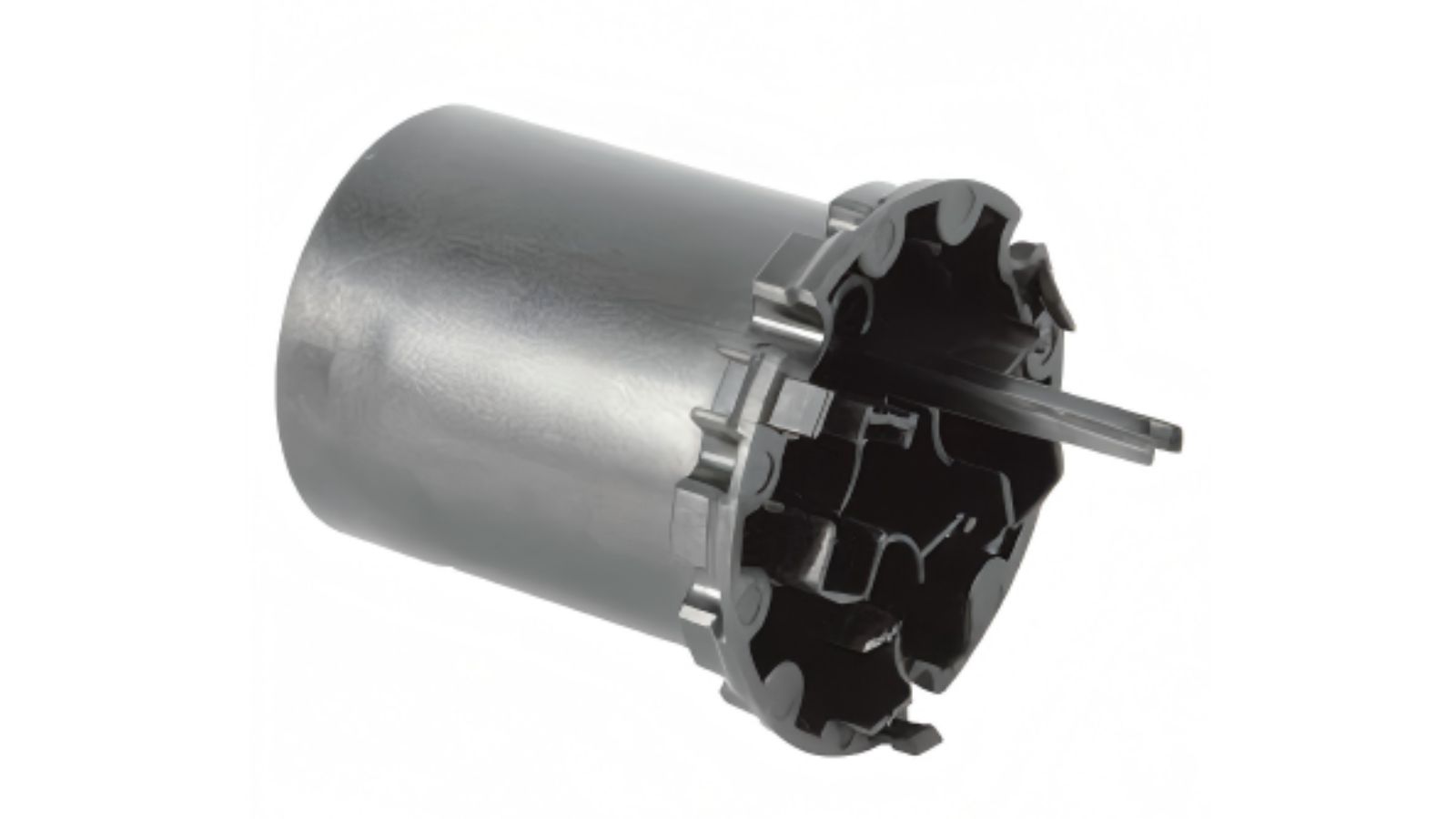
Insert Molding and Overmolding for Connectors and Protection
Insert molding places a pre-formed component, usually metal, into the mold cavity before plastic is injected around it. This is the standard method for producing electrical connectors with integrated metal terminals, threaded inserts, or bus bars. The result is a single part with a permanent bond between metal and plastic.
Overmolding adds a second layer of material over an existing molded or assembled part. Common uses include soft-touch grips on handheld electronics, strain relief on cable assemblies, and environmental seals on sensor housings. Two-shot injection molding machines can perform overmolding in a single cycle for higher efficiency.
In-Mold Electronics and Structural Electronics
In-mold electronics (IME) is a newer process that embeds printed circuits, LEDs, sensors, or capacitive touch elements directly into a molded plastic part. The process typically starts with printing conductive inks and functional components onto a flat film, then thermoforming the film into a 3D shape, and finally back-molding it with plastic.
Injection molded structural electronics (IMSE) takes this further by integrating circuit design into the structure of the part itself. The result is thinner, lighter assemblies with fewer discrete components and reduced assembly steps.
Thermoforming, Circuit Design, and Capacitive Touch Interfaces
IME and structural electronics rely on thermoforming to shape the printed circuit film before it enters the injection mold. This step must be tightly controlled to avoid cracking conductive traces or displacing components.
Capacitive touch interfaces are one of the most visible applications. Automotive interior panels, appliance controls, and consumer electronics use IME-based touch surfaces that replace mechanical buttons with sleek, sealed panels. These parts combine circuit design, surface decoration, and structural plastic in a single integrated component.
Design, Quality, and Secondary Operations
DFM Priorities for Electronic Part Geometry and Assembly
Design for manufacturability (DFM) review should begin before mold design starts. For electronic parts, critical DFM priorities include:
- Uniform wall thickness to prevent sink marks and warpage during thermal cycling
- Draft angles that allow clean ejection without distorting thin features
- Gate placement that avoids cosmetic surfaces and weld lines near structural areas
- Boss and rib design that supports screw retention and board mounting without excessive material buildup
A thorough DFM process also considers how parts will be assembled. Snap-fit features, alignment pins, and cable routing channels should be validated against the full device assembly, not just the individual part.
Inspection, Validation, and ISO 9001 Quality Systems
Quality control for electronics injection molding involves dimensional inspection, visual checks, and functional validation. Coordinate measuring machines (CMMs), 3D scanners, and first article inspection (FAI) reports verify that parts meet drawing specifications before production ramps up.
Manufacturers serving electronics programs typically operate under ISO 9001 quality management systems. For automotive electronics, IATF 16949 certification adds another layer of process control and traceability.
Pad Printing, Screen Printing, and Other Secondary Operations
Many electronic parts require markings, labels, or surface treatments after molding. Common secondary operations include:
- Pad printing for logos, regulatory marks, and pin labels on connectors
- Screen printing for larger graphics or control panel legends
- Laser engraving for permanent, wear-resistant markings
- Ultrasonic welding for joining enclosure halves without adhesives
- Threaded insert installation using heat or ultrasonic methods
Production Planning and Supplier Selection
Prototype-to-Production Workflow for Electronics Programs
A typical electronics injection molding program follows this sequence:
- Part design and DFM review based on 3D models or sample parts
- Prototype tooling for dimensional and functional validation
- Mold flow analysis to optimize gate location, cooling, and fill balance
- Production tooling built in hardened steel for target volume and lifespan
- First article inspection and process capability study
- Pilot production run to confirm cycle time, yield, and repeatability
- Mass production with ongoing quality monitoring
At this stage, cycle times for small electronic parts can drop under 30 seconds, utilizing automated ejection, robotic part handling, and multi-cavity molds to maximize output.
On-Time Delivery, Tooling Support, and Supply Chain Coordination
On-time delivery depends on realistic lead time estimates, tooling readiness, and material availability. A capable supplier maintains tooling in-house or through closely managed partners, tracks mold maintenance schedules, and keeps safety stock of critical resins.
For programs that include assembly, packaging, or sourced components, supply chain coordination becomes even more important. Turnkey manufacturing partners that handle mold making, molding, machining, assembly, and packaging under one roof reduce handoff delays and communication gaps.
Partner with Moldie for Precision in Electronics Manufacturing
Bringing an electronic device to market requires more than just shooting plastic into a mold. It demands tight tolerances, rigorous material selection, and a manufacturing partner who understands the complexities of integrating plastics with sensitive electronics. Whether you are developing high-temperature connectors, complex insert-molded components, or sleek capacitive touch interfaces, the right partner mitigates risk and accelerates your time-to-market.
At Moldie, we combine in-house precision tooling with ISO 9001 and IATF 16949 certified quality systems to deliver flawless electronic components at scale.
Ready to optimize your next electronics program? Contact our engineering team and upload your 3D CAD files to discuss material selection, tooling strategies, and prototyping today.


