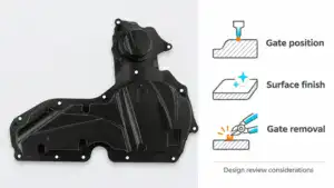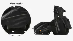
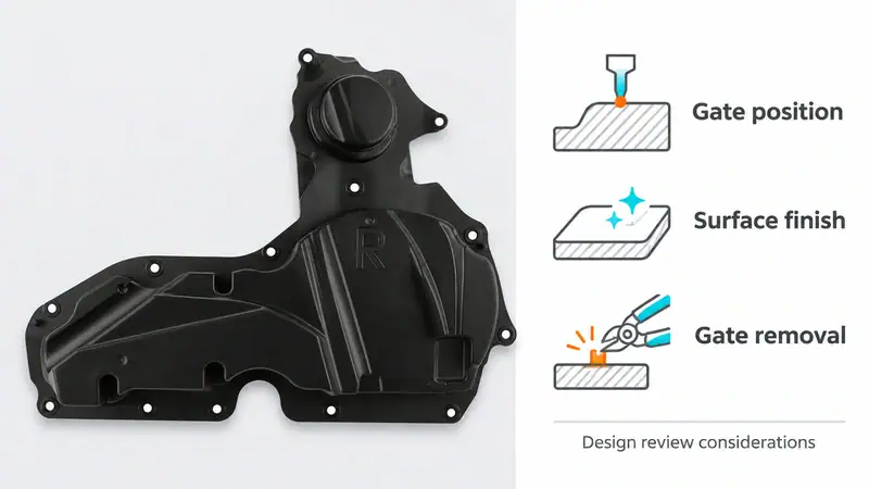
Injection molding gate selection affects more than how a cavity fills. It influences the visible gate mark, dimensional consistency, trimming labor and cost per accepted part. For OEM buyers and engineering teams, the right design must meet the drawing and appearance standard while supporting repeatable production at the quoted volume.
This guide focuses on eight common gate designs used in commercial molding projects. It explains where each fits, what trade-offs to review and which details to confirm with a supplier during design for manufacturability, or DFM, before approving the mold.
What a gate does in an injection mold
A gate, also called an ingate, is the opening through which molten resin enters the cavity. A conventional cold-runner mold feeds it through a sprue and runner; a direct sprue gate connects the sprue to the part. Hot-runner molds deliver resin through heated channels and nozzles.
Gate type, location, size and number work together. They influence pressure loss, shear, packing access, flow-front meeting points and the mark left after separation. A gate that fills the part successfully can still be unsuitable if its vestige interferes with sealing, assembly or an approved cosmetic surface.
A practical comparison of gate families
| Production requirement | Options to evaluate | Main approval issue |
| Simple tooling and accessible adjustment | Direct or edge gate | Gate removal and permitted vestige |
| Control of melt entry on a flat or sensitive part | Fan or tab gate | Flow distribution and trimming |
| Automatic cold-runner separation | Tunnel or pinpoint gate | Clean break and runner extraction |
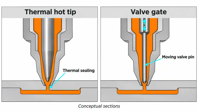
| Direct hot-runner feed | Thermal hot tip or valve gate | Gate appearance, controls and upkeep |
These options cover many general molding projects. Specialized gates may be needed for unusual geometries or strict concentricity requirements. Supplier terminology also varies: ask for a section drawing and separation sequence, especially when a quotation simply says “pin gate.”
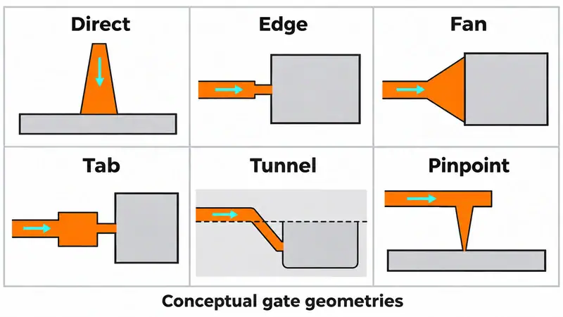
Cold runner gates for general and flat parts
1. Direct or sprue gate
The sprue feeds one cavity directly, providing a short flow path with relatively low pressure loss. Consider it for a single-cavity part with a robust, accessible gate area. A substantial attachment remains for removal, so approve the finished surface and account for sprue cooling and finishing in the cycle and unit-cost estimate.
2. Edge or side gate
An edge gate enters at the parting line. Its accessible geometry makes machining, maintenance and trial adjustments straightforward for many housings and industrial parts. Define the trimming method and allowable edge burr or notch. A convenient entry point still needs checking against weld-line position, packing demand and assembly clearances.
3. Fan gate
A fan gate widens toward the cavity to spread melt across a broader entry. It is worth evaluating for wide, relatively flat components where concentrated entry would create an uneven front. Review the gate thickness profile and fill progression; widening the entrance alone does not ensure balance. Budget for removal along the wider attachment.
4. Tab gate
A tab gate feeds the part through a sacrificial tab, helping manage melt entry and keep some entry-related stress or blemishes outside the finished component. It can be considered for shear-sensitive or appearance-sensitive applications. The tab consumes material and requires removal; agree on the permitted cut surface and verify the benefit with the actual resin.
Cold runner gates that support automatic separation
5. Submarine or tunnel gate
An angled tunnel feeds the part below the parting line and normally shears during ejection. This can reduce manual handling on repeat production. Before approval, check whether the resin and runner can tolerate the required deformation. Inspect for tearing, whitening, retained fragments and inconsistent vestige during repeated cycles.
6. Pinpoint gate
A conventional pinpoint gate uses a small entry, commonly in a three-plate cold-runner mold. The opening sequence separates the gate and releases the runner. It provides placement flexibility beyond the part edge, but adds mold movement and runner handling. Confirm adequate filling and packing through the restricted entry and approve the small mark it leaves.
Hot runner gates for production programs
7 Thermal hot tip gate
A heated nozzle feeds the cavity directly without a cold runner attached at that entry. Thermal conditions govern sealing and separation at the gate. Review the vestige, possible stringing or drool, and resin residence time. The production case should include color changes, startup scrap and heater or tip maintenance, as well as runner-material savings.
8 Valve gate
A moving pin opens and closes the hot-runner gate mechanically. Individually controlled gates can support sequential filling and help manage flow-front meeting locations on suitable parts. Compare the benefit with system cost, actuation, controls and maintenance. A valve gate still leaves a witness mark; approve its appearance and check the operating sequence during sampling.
How to select a gate design for an OEM project
Begin with the exact resin grade, local wall thickness, flow length and permitted witness area. A glass-filled grade, a brittle resin and an unfilled material may need different entry and separation conditions. Gate dimensions should follow material guidance and analysis, then be confirmed by trials; a single gate-to-wall ratio is not a release specification.
Review gate location together with ribs, holes, sealing faces and critical load paths. Feeding a thicker region can help preserve packing access, but the full flow pattern determines where weld lines and air traps appear. Multiple gates may shorten the flow path while creating additional meeting fronts. Simulation helps compare proposals; physical samples establish whether the result is acceptable.
For purchasing, compare the cost per accepted part over the forecast program volume. Include tooling investment, runner material, trimming, inspection, scrap, cycle time and maintenance. A hot runner or automatic gate is justified when its production benefits cover the additional investment and support requirements. There is no volume threshold that applies to every project.
What to confirm before mold and sample approval
- On the DFM drawing: gate type, count, location and section, plus permitted vestige and prohibited surfaces.
- In the production plan: runner handling, degating method, finishing and inspection responsibility.
- At mold trials: fill progression, cavity balance, pressure demand, packing response and gate separation over repeated cycles.
- For acceptance: appearance under agreed viewing conditions, dimensions after specified conditioning, and functional checks at affected features.
For gates that seal by freezing, a hold-time and part-weight study can help establish effective gate seal. Valve-gated tools also require checks of closure timing and packing response. Approve a production window that meets quality and cycle requirements, rather than relying on one good-looking shot.
Request a gate design review from Moldie
Send Moldie your 2D and 3D files, resin grade, annual demand, cavity target and cosmetic requirements. Mark sealing surfaces, load-bearing features and areas where gate removal is unacceptable. Our project workflow includes DFM and simulation, followed by sampling and validation, so gating decisions can be reviewed before production approval. Contcat us and discuss your injection mold project.