Gate injection molding plays a key role in shaping how molten plastic flows in plastic injection molding. It determines how efficiently the material fills the cavity, how strong the area around the gate is, and how clean its surface looks. Understanding gate injection molding helps achieve better quality, reduce waste, and improve production efficiency.
In this guide, we at Moldie will help you explore the fundamentals of gate injection molding and how materials and applications dictate the use of gates. By learning the basics, you will be able to make better decisions when optimizing your production process and product.
Fundamentals of Gate Injection Molding
What Is a Gate in Injection Molding?
As a component of a plastic injection mold, a gate can be defined as the small opening that connects the runner system to the mold cavity. It allows molten plastic to flow into the cavity during the injection molding process. Their size, shape, and type determine how easily the material fills the mold and how the gate separates after cooling.
Common gate types include edge, direct (sprue), fan, pinpoint, tunnel, and more. Each type serves different part geometries and production needs. A properly sized gate helps maintain consistent plastic flow and prevents issues such as short shots or excessive stress.
Role of Gates in the Injection Molding Process
Gates control how molten plastic enters the mold cavity and how pressure builds during filling and packing. They act as a flow regulator, balancing speed and temperature to ensure even distribution of material.
The gate also influences cooling, cycle time, and degating. A smaller gate cools quickly and allows faster cycles but may restrict flow. A larger gate improves filling but can leave a more noticeable gate mark or gate vestige.
Proper gate design reduces defects such as sink marks, weld lines, or voids for molded parts. It also helps maintain uniform density and dimensional accuracy across the part. Engineers adjust gate size, shape, and position to match the material’s viscosity and the part’s thickness and complexity.
Gate Location and Its Impact
Gate location determines where the plastic flow begins and how it spreads through the mold cavity. Poor placement can cause uneven filling, air traps, or visible flow lines that reduce part quality.
Placing the gate near thicker sections helps control shrinkage and reduces internal stress. For aesthetic parts, designers often hide the gate on non-visible surfaces to minimize gate marks.
Balanced gate placement supports consistent flow paths in multi-cavity molds. The table below shows how location affects performance:
| Gate Location | Effect on Flow | Impact on Appearance |
|---|---|---|
| Centered | Even filling, low stress | Minimal marks |
| Edge | Faster filling, possible weld lines | Visible marks |
| Hidden (sub-gate) | Clean surface | Marks on angled or hidden surfaces |
Types of Injection Molding Gates

Manual Trim Gates
These gates are simple and cost-effective but require an extra trimming step after the part is molded.
- Sprue Gate: A large gate directly from the sprue to the part. Best for large, single-cavity molds where appearance isn’t critical. It is simple but leaves a visible mark.
- Edge Gate: Located along the mold’s parting line. It’s a versatile, all-purpose gate used for a wide variety of parts and is easy to machine.
- Tab Gate: Uses a small tab between the runner and part to reduce stress and prevent flow marks. Ideal for flat parts needing a better surface finish.
- Fan Gate: Widens the flow path to spread plastic evenly across a broad area. Excellent for thin, wide parts to prevent warping.
Automatic Gates
These gates increase efficiency by removing the need for manual trimming, making them ideal for high-volume production.
- Tunnel Gate (Submarine Gate): Angled gate that shears off automatically during ejection. It hides the gate mark below the parting line, perfect for small, round parts.
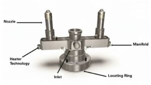
- Pin Gate: A very small, circular gate often used in hot runner systems. It leaves a minimal, clean mark and is common for high-precision cosmetic parts like lenses.
Gates for Specific Flow Needs
Some parts need specialized gates to control how the plastic enters the cavity.
- Diaphragm Gate: Feeds material evenly around a central core, ideal for cylindrical parts to ensure balanced flow and strength.
- Cashew Gate: A curved, tunnel-like gate that feeds plastic from behind the part, completely hiding the gate mark on visible surfaces.
You can find a more detailed analysis on how each type of gate functions exactly and how their designs differ in our guide on the types of injection molding gates.
Materials and Applications’ Influence on Gate Choice
Thermoplastics and Material Flow
Different thermoplastics have unique melt viscosities and cooling rates that influence gate selection. Amorphous materials like ABS, PS, and HIPS flow easily and tolerate small gate openings such as pin point or tunnel gates. These gates help maintain a good surface finish and allow automatic separation.
Crystalline plastics like POM or PA need balanced gate sizes for proper packing because of their rapid crystallization and high shrinkage rates. Glass-filled resins require gates designed to minimize excessive shear and fiber breakage, such as tab gates or appropriately sized edge gates.
For transparent materials like PC and PMMA, fan or tunnel gates reduce flow lines and optical defects. PVC and HDPE often use edge or direct gates that provide stable flow and easy trimming. Matching gate type to material flow ensures consistent filling and minimizes stress or warpage.
Part Geometry and Wall Thickness
Part shape and wall thickness determine how melt enters and fills the cavity. Thick-walled parts or large structural components often use direct or edge gates to shorten flow paths and maintain pressure. These gates reduce the risk of short shots and uneven cooling.
Flat parts such as covers or consumer electronics enclosures benefit from fan or tab gates. These distribute material evenly and help maintain a smooth surface. For cylindrical or deep parts, tunnel or pin point gates are preferred because they allow hidden gate placement and clean ejection.
Gate location should promote balanced flow and avoid weld lines. Tool designers often use flow analysis to choose a gate that supports efficient filling and high part quality.
Production Volume and Efficiency
Production scale directly affects gate choice and mold design. High-volume molds often use pin point or tunnel gates for automatic degating, which shortens cycle time and improves production efficiency. These gates support multi-cavity molds and reduce manual labor.
For low-volume runs or prototype tools, edge or direct gates are more cost-effective. They are easier to machine and modify but require manual trimming.
When annual output is high, automated gating systems reduce downtime and wear. Selecting a gate that matches production volume helps balance tooling cost, part quality, and long-term reliability.

