The parting line is an injection molded plastic junction where halves meet during the molding process. Ensuring a high line is essential for product functionality and aesthetics. However, many manufacturers fully use the parting line and control it. This article seeks to determine what determines part line and mold designers and process engineers can influence it.
Understanding Parting Lines
The parting line may not be noticeable. However, when you’re delving into the intricacies of injection molding, comprehending parting lines is crucial. They’re the blueprint for mold design and affect the aesthetics and function of your finished product.
Definition and Importance
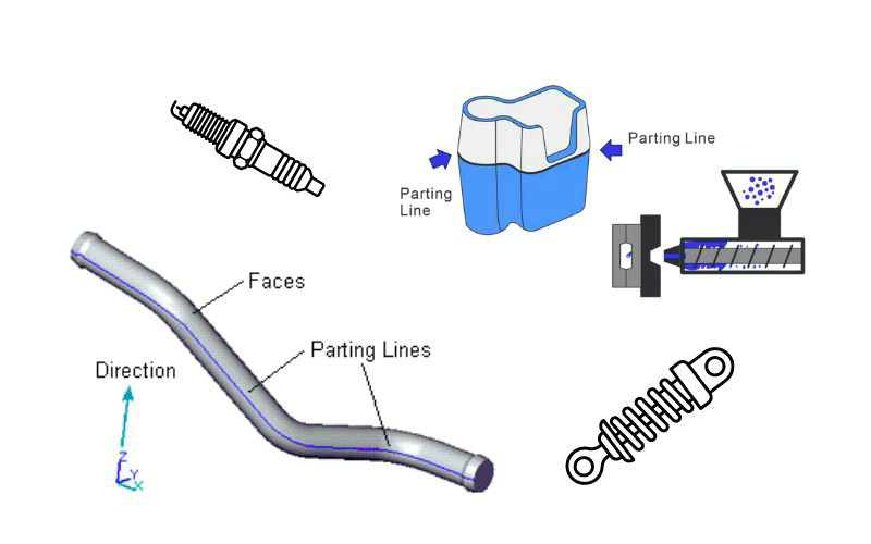
The parting line in plastic injection molding refers to the exact point where two different halves of the mold meet together. This line is more than a mere seam; it plays a pivotal role in the molding process, impacting your product’s integrity and appearance. As a designer, it’s essential to understand that a well-designed parting line ensures your mold aligns correctly and releases the finished product without defects.
- Why It Matters:
- Aesthetics: Minimizes visible seams on the final product.
- Function: Ensures accurate alignment of mold halves for flawless production.
- Ease of Manufacture: Aids in simplifying the molding process.
Types of Parting Lines
Parting lines are categorized based on their orientation and complexity within the mold design.
- Vertical Parting Line: This line runs perpendicular to the mold opening and is suitable for simpler part geometries.
- Where You’ll See It: Often visible as a straight line on the sides of products.
- Curved Parting Line: As the name suggests, this line is curved, following the contour of more complex designs.
- Benefits: Allows for more intricate part shapes.
- Stepped Parting Line: A more complex form that involves changes in the parting line height across the mold surface.
- Designer’s Challenge: Requires a nuanced approach to accommodate the part’s features.
Here’s a quick reference for you:
| Parting Line Type | Orientation | Complexity | Ideal Usage |
|---|---|---|---|
| Vertical | Perpendicular to mold opening | Low | Simple geometries |
| Curved | Along the part’s contours | Medium | Complex shapes |
| Stepped | Multiple levels | High | Parts with varying heights |
Parting Line Design Considerations
When designing for injection molding, aligning your parting lines correctly and ensuring proper draft angles are critical for both the manufacturability and the cosmetic finish of your product.
Incorporating Draft Angles
Draft angles are slight tapers included in the design of molded parts, making it easier to release them from the mold. Ideal draft angles depend on the depth of the mold: the standard rule is to apply 1 degree of draft per 1 inch of depth. However, for a smoother demolding process, you should consider adding an additional 1 to 2 degrees. This is especially vital in areas near the parting lines, as it reduces the risk of damage to the part during ejection.
Surface Finish and Aesthetics
Your part’s surface finish can be greatly affected by the parting line’s placement. It’s crucial to position parting lines on non-cosmetic surfaces whenever possible. Any mismatch along the parting line can lead to finishing defects which can be both unsightly and difficult to repair. When approaching design for manufacturability (DFM), a careful analysis of how the parting line interacts with the finished surface is a must.
- Surface Finish Considerations: Position parting lines away from cosmetically critical areas.
- DFM: Analyze parting line interactions with intended surface finish.
Mold Configuration and Assembly
In injection molding, accurate mold configuration and proper assembly are crucial for ensuring high-quality finished parts. Your understanding of the core and cavity layout, along with the alignment of mold halves, is fundamental for a smooth manufacturing process.
Core and Cavity Layout
Your mold design encompasses two essential components: the core and the cavity. These components work together to form the negative space that will shape your part. The core is essentially the internal part of your mold that creates hollow portions of the finished piece, while the cavity refers to the external shape that the molten material will fill.
To ensure precision in your design, keep the following in mind:
- Material Flow: Consider the flow of plastic to avoid defects.
- Cooling System: Integrate an effective cooling system within the layout to control the mold temperature, reducing warping and stress.
- Ejection System: Plan for an ejection system that allows the finished product to be safely removed without damage.
Mold Halves and Opening Direction
The assembly of your mold involves two halves often referred to as the fixed half and the moving half. Here’s a quick guide:
- Fixed Half: This portion of the mold attaches to the stationary plate of the injection molding machine.
- Moving Half: It is fixed to the moving platen and opens and closes along the mold opening direction.
Mold Opening Direction: The direction in which the mold opens is critical and defines the parting line’s location. Typically, molds open in the vertical direction, but considerations such as complex shapes or specific designs might necessitate an alternative approach like horizontal opening. Always ensure the parting line is clearly defined to achieve proper alignment during mold closure.
Proper consideration of these elements in your mold design and assembly process helps in achieving a flawless and efficient molding operation.
Manufacturing Process and Part Ejection
In this section, you’ll explore the injection molding cycle and the ejection system, two critical components in manufacturing that influence the final quality of your plastic parts.
Injection Molding Cycle
The injection molding process begins with mold preparation. Here, the mold, comprising two halves known as the cavity and core, is secured in the machine’s clamping unit. The molding cycle then proceeds with the following steps:
- Closing: The mold is closed by the clamping unit, making it ready for injection.
- Injection: Molten plastic is injected into the closed mold under pressure.
- Cooling: The plastic is allowed to cool and solidify, forming the final part.
- Opening: Once cooled, the mold opens to expose the solidified part.
Throughout this cycle, engineers must ensure that each step is carefully controlled to prevent issues like flash, which is excess material that spills out of the mold cavity.
Ejection System and Considerations
Once the injection mold opens, the part must be ejected without damage:
- Ejector Pins: The most common way to eject the part is through ejector pins – rods that push the piece out of the mold. The position and force of these pins are critical to prevent deformation.
- Avoiding Flash: Flash occurs when the molten plastic seeps into the seams between the mold’s halves. Your ejector system should not contribute to flash formation by misaligning with the part.
In conclusion, understanding the intricacies of the injection molding cycle and the proper execution of ejection strategies ensures the flawless creation of injection-molded parts, where your role as an engineer is to monitor and refine these systems continually.
Troubleshooting and Optimization
In injection molding, you’ll face challenges related to defects and the functionality of your parts. By addressing these issues head-on, you can ensure high-quality results that meet both visual and functional demands.
Addressing Defects and Flash
When dealing with defects such as flash, which is excess plastic along the parting line, you need to assess the mold with precision. Here are key steps to resolve these issues:
- Inspect and Measure: Examine the vestiges of flash and measure their thickness to understand the extent of the problem.
- Adjust Clamp Force: If the clamp force is insufficient, increase it to prevent molten plastic from escaping.
- Ensure Proper Tolerances: Double-check the tooling design to maintain tight tolerances, helping to minimize flash.
Enhancing Functionality and Fit
To improve the functionality and fit of your components:
- Review Design for Stress Points: Identify areas where improper fit could cause stress and lead to defects.
- Test and Refine: Iteratively test your mold adjustments to ensure they meet desired cosmetic and functional standards.
By taking a systematic and attentive approach to these aspects, you can enhance the visual quality and functionality of your injection molded parts, ensuring they are free from defects and fit for purpose.
Advanced Parting Line Concepts
When designing injection molded parts, advanced parting line concepts involve a structured approach to managing complex geometry and ensuring manufacturability. Let’s explore the nuances of multi-step parting lines and the use of design analysis tools.
Multi-Step and Complex Parting Lines
Your designs may sometimes necessitate parting lines that can’t be addressed with simple, straight guidelines—this is where multi-step and complex parting lines come into play. These advanced strategies are essential when dealing with intricate geometric designs. Traditional parting lines are often straight and lie in a single plane, but multi-step parting lines zigzag across different planes, accommodating geometry with undercuts or other complex features.
- Comprehensive parting line designs take into account these factors:
- Side-actions: These are mechanisms within the mold that allow for lateral movement of components to form and release features not parallel to the mold opening.
- Camouflage: Skillful parting line placement can help conceal these lines, making them less noticeable on the final product.
By thoughtfully implementing multi-step parting lines, you can enhance both the aesthetics and functionality of your products. Remember to always iterate your designs with the potential complexities of parting lines in mind, anticipating the need for such advanced techniques.
Design Analysis and Software Tools
Leveraging CAD packages and design analysis software simplifies the creation and refinement of these advanced parting lines. These tools allow you to visualize how parting lines interact with your product’s geometry and to make design changes prior to mold construction, saving you time and resources.
- Key functions of design analysis tools include:
- Detection of areas where a simple parting line is not feasible.
- Simulation of mold opening and closing to identify potential issues with the proposed parting line.
When you use a CAD program equipped with specific mold design features, you’re armed with the power to execute intricate parting lines with precision. Use these programs to evaluate the manufacturability of your design, ensuring that your part can be successfully molded with the selected parting line strategy.
As you navigate these advanced parting line concepts, keep revisiting your CAD drawings and simulations to refine the layout for an optimal mold design. This iterative process, aided by advanced software tools, will facilitate the creation of efficient and aesthetically pleasing injection molded parts.
n conclusion, the parting line is a d
