What is a Surface Finish in Injection Molding?
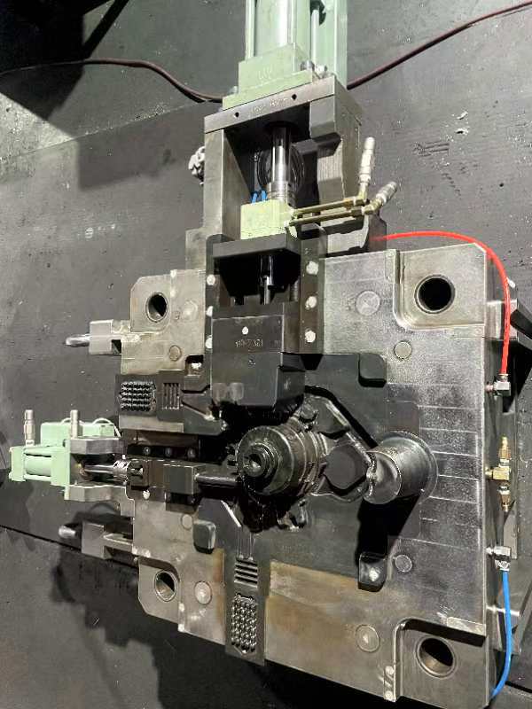
In the realm of injection molding process, the chosen surface finish can significantly affect both the appearance and functionality of the final product.
Definition of Surface Finish
A surface finish refers to the texture of the surface of a part that has been manufactured through injection molding. It includes the level of gloss, roughness, and pattern imparted on the surface of the molded part. This finish is determined by the quality of the mold itself as well as the materials used in the injection moulding process. Various surface finishes can be achieved, including matte, textured, or highly glossy finishes, which are attained through different post-molding processes such as polishing or applying textures to the mold before production.
Importance of Surface Finish in Injection Molding
The surface finish in injection molding is paramount because it directly impacts the appearance and functionality of the part.
Importance for Visual Appeal
- A smooth, glossy finish (SPI A grades) provides a high-end, polished look suitable for cosmetic parts, lenses, etc.
- Semi-gloss (SPI B grades) and matte (SPI C grades) finishes can hide imperfections like flow lines, weld lines, and tooling marks to improve appearance.
- Textured finishes (SPI D grades) offer unique aesthetic options like leather grain, woodgrain, geometric patterns, etc.
Importance for Functionality
- Textured finishes can provide improved grip and slip resistance for products like handheld devices, steering wheels, etc.
- Specific finishes can enhance paint and label adhesion on the molded part surface.
- Texturing allows gases to escape the mold and can be used to create undercuts.
- Surface roughness affects friction and wear resistance which may be important for mechanical parts.
How are SPI, VDI, and Mold-tech Surface Finish Standards Applied?
Surface finish standards such as SPI and VDI define the cosmetic quality and functionality of the molded parts by specifying the gloss, texture, and roughness parameters. These standards ensure that the surfaces meet predetermined criteria crucial for the product’s performance and aesthetic appeal.
Overview of SPI Mold Finish Standards
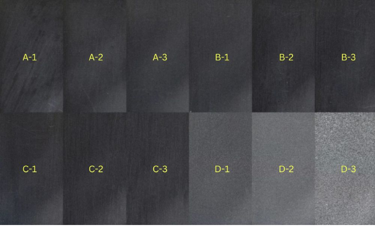
The Society of the Plastics Industry (SPI) has established a classification system for injection mold surface finishes. This system categorizes finishes into glossy (A), semi-glossy (B), matte (C), and textured (D) grades, each with specified levels of gloss and roughness:
- SPI A is the pinnacle, providing highly polished, glossy finishes. It often involves the labor-intensive use of diamond buffing, suitable for parts where a premium look is paramount.
- SPI B offers semi-glossy finishes, achieved through finer grit sanding and less intensive polishing. These finishes are a balance of aesthetic appeal and cost-effectiveness.
- SPI C reflects a standard matte finish, typically produced with stone abrasives.
- SPI D creates the most textured, non-glossy surfaces, suitable for parts where grip or non-reflective properties are desired.
Across this spectrum, exact roughness values are imparted upon the mold surface, ensuring the part maintains the intended appearance.
| SPI Standard | Finish (Grade) | Finish (Type) | Finishing Method | Typical Surface Roughness (Ra µm) |
| A-1 | Glossy | Super High Glossy | Grade #3, 6000 Grit Diamond Buff | 0.012 to 0.025 |
| A-2 | Glossy | High Glossy | Grade #6, 3000 Grit Diamond Buff | 0.025 to 0.05 |
| A-3 | Glossy | Normal Glossy | Grade #15, 1200 Grit Diamond Buff | 0.05 to 0.10 |
| B-1 | Semi-Glossy | Fine Semi-Glossy | 600 Grit Paper | 0.05 to 0.10 |
| B-2 | Semi-Glossy | Medium Semi-Glossy | 400 Grit Paper | 0.10 to 0.15 |
| B-3 | Semi-Glossy | Normal Semi-Glossy | 320 Grit Paper | 0.28 to 0.32 |
| C-1 | Matte | Fine Matte | 600 Grit Stone | 0.35 to 0.40 |
| C-2 | Matte | Medium Matte | 400 Grit Stone | 0.45 to 0.55 |
| C-3 | Matte | Normal Matte | 320 Grit Stone | 0.63 to 0.70 |
| D-1 | Textured | Satin Textured | Dry Blast Glass Bead | 0.80 to 1.00 |
| D-2 | Textured | Dull Textured | Dry Blast #240 Oxide | 1.00 to 2.80 |
| D-3 | Textured | Rough Textured | Dry Blast #24 Oxide | 3.20 to 18.0 |
Understanding VDI 3400 Standards
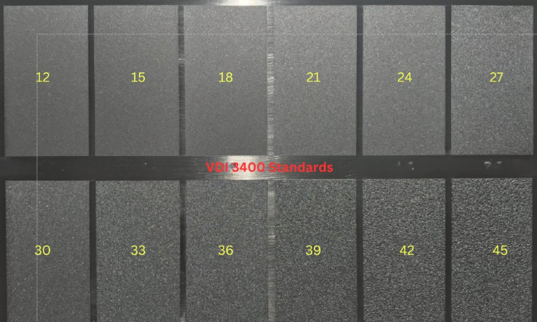
VDI 3400 standards originate from the Verein Deutscher Ingenieure, the Association of German Engineers. These standards encapsulate a range of textures from very smooth to highly textured, enabling precise control over the tactile and visual qualities of the injection molded part. Unlike SPI, VDI 3400 uses a set of 3D molds that exhibit different levels of roughness corresponding to specific grades, such as VDI 12 to VDI 45. These physical samples enable straightforward comparison and selection. The VDI 3400 standards apply to various materials and processing techniques and are particularly suited for achieving complex and detailed textures.
| VDI Value | Description | Applications | Surface Roughness (Ra µm) |
| VDI 12 | 600 Stone | Low polish parts | 0.40 |
| VDI 15 | 400 Stone | Low polish parts | 0.56 |
| VDI 18 | Dry Blast Glass Bead | Satin finish | 0.80 |
| VDI 21 | Dry Blast # 240 Oxide | Dull finish | 1.12 |
| VDI 24 | Dry Blast # 240 Oxide | Dull finish | 1.60 |
| VDI 27 | Dry Blast # 240 Oxide | Dull finish | 2.24 |
| VDI 30 | Dry Blast # 24 Oxide | Dull finish | 3.15 |
| VDI 33 | Dry Blast # 24 Oxide | Dull finish | 4.50 |
| VDI 36 | Dry Blast # 24 Oxide | Dull finish | 6.30 |
| VDI 39 | Dry Blast # 24 Oxide | Dull finish | 9.00 |
| VDI 42 | Dry Blast # 24 Oxide | Dull finish | 12.50 |
| VDI 45 | Dry Blast # 24 Oxide | Dull finish | 18.00 |
Mold-tech Surface Finish Standards
| Series | Texture Number | Texture Depth (inch) | Texture Depth (mm) | Minimum Draft Angle | Description |
| MT-A | MT-11010 | 0.001″ | 0.0254 mm | 1.5° | Fine matte sand-like finish |
| MT-A | MT-11020 | 0.0015″ | 0.0381 mm | 2.5° | Medium matte finish |
| MT-A | MT-11030 | 0.002″ | 0.0508 mm | 3° | Coarse matte finish |
| MT-A | MT-11040 | 0.003″ | 0.0762 mm | 4.5° | Very coarse matte finish |
| MT-A | MT-11050 | 0.0045″ | 0.1143 mm | 6.5° | Aggressive matte finish |
| MT-B | MT-11200 | 0.003″ | 0.0762 mm | 4.5° | Geometric pattern |
| MT-B | MT-11210 | 0.0035″ | 0.0889 mm | 5.5° | Geometric pattern |
| MT-B | MT-11220 | 0.004″ | 0.1016 mm | 6° | Geometric pattern |
| MT-D | MT-11550 | 0.0045″ | 0.1143 mm | 6.5° | Wood grain pattern |
| MT-D | MT-11555 | 0.006″ | 0.1524 mm | 9° | Coarse wood grain pattern |
How does Mold Texture Affect the Injection Molded Part?
Mold texture plays a crucial role in defining the aesthetics and functionality of injection molded parts. It directly influences surface roughness and can lead to various production challenges if not managed properly.
Role of Mold Surface in Injections
The surface of a mold is paramount in determining the quality of an injection molded part. During the molding process, the molten plastic material conveys the texture of the mold’s surface to the final product. The degree of polish on the mold surface can affect the paint adhesion; a highly polished surface results in a glossy finish that may be more challenging for paint to adhere to, whereas a textured surface offers better paint bonding. Similarly, certain textures can minimize the appearance of imperfections such as flow lines, which are visible lines on the surface of the molded part caused by the varying speeds at which the molten plastic flows.
Achieving Desired Surface Roughness
Texturing processes create specific patterns on the mold that are transferred onto the part surface. These patterns may range from very fine textures that slightly alter the part’s gloss to heavy textures that create a noticeable roughness. The selection of texture should align with the part’s intended use and the quality expectations of the end product. For instance, a leather-like texture may be used in automotive interiors for an enhanced grip and luxurious feel.
Common Mold Finishes Issues and Solutions
Flow Lines
Flow lines appear as wavy patterns or off-color streaks on the surface of the molded part. They are caused by variations in the cooling speed of the material as it flows through the mold at different rates.
Solutions:
- Increase the injection speed, pressure, and material temperature to ensure the mold fills before cooling
- Round the corners of the mold where wall thickness increases to keep flow rate consistent
- Relocate mold gates to create more distance from the mold coolant to prevent early cooling during flow
Jetting
Jetting manifests as worm-like swirls near thick gate areas. It is caused by temperature variations within the material flow, often due to gates that are too small or injection speeds that are too fast.
Solutions:
- Increase gate size and change side gates to lap gates
- Reduce injection speed to prevent excessive shear heating of the material
Sink Marks
Sink marks are small depressions or dimples that appear in thicker cross-sections of the part. They occur when the inner portion cools and shrinks more quickly than the outer portion.
Solutions:
- Increase the injection pressure and holding pressure to ensure proper packing
- Increase the gate size or change the gate position
- Redesign the part to have a more uniform wall thickness, with ribs and bosses not exceeding 60% of the nominal thickness
How to Choose the Right Surface Finish for Your Injection Molded Part?
Matching Surface Finish with Product Requirements
The product’s end use dictates the surface finish options. For items requiring high aesthetics, such as consumer products, a glossy finish may be necessary. Conversely, industrial parts may benefit from textured finishes for improved grip or paint adherence. SPI finishes (Society of the Plastics Industry standards) like SPI A-2 are often used when a high polish is needed, while an SPI C-1 finish might suffice for non-cosmetic components.
Draft Angle
Incorporating the appropriate draft angle into the part design is non-negotiable to ensure proper mold release. A steeper draft angle will facilitate easier demolding, which may allow for the usage of more aggressive textures without risking part integrity.
Moulding Material
The chosen moulding material influences the attainable surface finish. Harder plastics can achieve higher gloss levels, while softer materials may require a different approach to achieve similar effects. Part designers must understand how the material interacts with the finish to meet the desired quality.
Tooling Cost
Higher levels of surface finish elevate tooling costs due to increased machining and polishing time. Product designers must balance the aesthetic requirements with economic feasibility, keeping in mind that certain finishes necessitate more intricate and labor-intensive tooling processes.
Mold Tool Material
The mold tool material determines its longevity and the level of detail it can impart. For long production runs or highly detailed finishes, robust tool steel is beneficial. In scenarios where cost-savings are paramount, aluminum molds may be used, with the caveat that they may wear more quickly or not achieve the same level of detail as steel.

