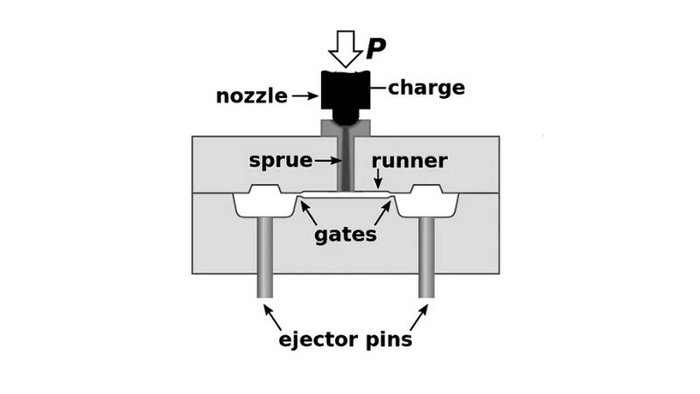
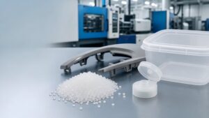
Injection molding is like running a really cool assembly line in miniature, and ejector pins are your tiny co-workers ensuring every piece comes out right. These pins are key players, often overlooked, but they do the heavy lifting when it comes to popping out your freshly molded parts from their confining molds. Imagine making a perfect plastic part – your ejector pins make sure it gets out into the world without a hitch. They push the part out once it’s cooled down, meaning less hassle for you and a quicker route from design to real-life product.
Choosing the right ejector pins is crucial because they’ve got to match the design and type of your product. They come in different shapes and sizes, each with a special knack for dealing with specific part surfaces or shapes. Think of your ejector pins as customizable helpers; you pick and position them in the mold so they apply just the right amount of force. This way, they don’t leave marks or damage what you’ve made.
Key Takeaways
1. What are ejector pins and what is their purpose?
Ejector pins are part of the ejection system that pushes the cooled and hardened plastic part out of the mold after the injection molding process. This allows the efficient removal and ejection of molded parts.
The mold maker spends significant time and effort machining and polishing the mold cavities to ensure high quality plastic parts. However, low quality ejector pins can undo this work and damage the mold if they fail.
2. What is the core pin?
A core pin is a key component used in injection molds and die casting molds to create internal features and holes in molded or cast parts.
3. What are some types of ejector systems?
- Plate ejection systems use a plate to push out parts
- Air ejection blows air to eject parts, good for thin parts
- Ejector pins directly push on the part to eject it
4. What should be considered when positioning ejector pins?
- Pins should push on surfaces with enough area to eject the part
- May need to add ejector pads if the surface area is limited
- Pin placement should minimize visible marks on the final part
5. What issues can occur with ejector pins?
- Can leave marks on the molded part
- May not fully retract due to resistance or binding
- Can damage or scratch molded parts if not properly aligned
Design Considerations for Ejector Pins
When you’re setting up your injection molding project, nailing the ejector pin design is crucial. Not only do they help eject the part from the mold, but they also play a big role in the final quality of your products.
Mold Design and Pin Placement
You gotta get the mold design spot on. Your ejector pins should be evenly spread out across the part to avoid distortion during ejection. Make sure there’s sufficient distance between ejector pin holes and other features of the mold to prevent any mishaps.
- Ejector Pin Placement: Aim for strategic pin positions that support the mold part well.
- Venting: Proper venting is key to prevent vacuum formation that could mess up part ejection.
Size, Position, and Draft Angles
Size matters here. You don’t want your pins to be too small that they can’t eject the part, or so big they damage it. The correct position ensures a smooth ejection, and adding draft angles to the part design will make this even easier.
- Size: Use larger pins for hefty parts but don’t go overboard.
- Position: Align pins with thicker sections of the part for efficient ejection.
- Draft: Ensure your part has a draft angle for easier ejection and less wear on your pins.
Materials and Heat Treatment
Your ejector pins need to be tough. Usually, through-hard ejector pins are chosen for their durability, but for more abrasive and high-temperature materials, black ejector pins can be your go-to. Heat treatment is a big deal – it strengthens the pins so they can do their job over and over again without bending or breaking.
Ejector Pin Types and Their Uses
In the realm of injection molding, ejector pins are like your unsung heroes, swiftly and reliably demolding parts. Let’s break down the types you’ll use most often.
Standard Ejector Pins
Standard ejector pins are your go-to for the majority of projects. They’re made of durable, heat-treated steel that can take the heat up to 200°C, giving them a consistent hardness. Think of these pins as the sturdy all-rounders in your toolbox.
- Materials: Typically through-hardened steel
- Heat Resistance: Up to 200°C
- Applications: General plastic ejection
Blade and Sleeve Options
Moving to more specialized gear, blade and sleeve options offer you flexibility. Blade ejector pins have a thin, flat form ideal for ejecting parts with thin walls or intricate features without leave behind marks.
Ejector sleeves, on the other hand, give you that snug fit for cylindrical or round-shaped ejectors. They envelop the pins, adding an extra layer of guidance and support during part ejection.
- Blade Ejector Pins:
- Shape: Thin, flat profile
- Best For: Delicate parts with minimal ejection marks
- Ejector Sleeves:
- Function: Add support to ejector pins
- Best For: Cylindrical or round ejectors
Each type of ejector pin plays a specific role in ensuring that your molded parts pop out cleanly and with precision. Remember, choosing the right pin for the right job is key to a smooth molding operation.
Understanding the Ejection Process
The ejection process in injection molding is all about precision and timing. Get this right, and your parts come out cleanly every time.
Mechanics of Ejection
Your ejector system kicks into gear once the molded part has cooled. Here’s how it unfolds:
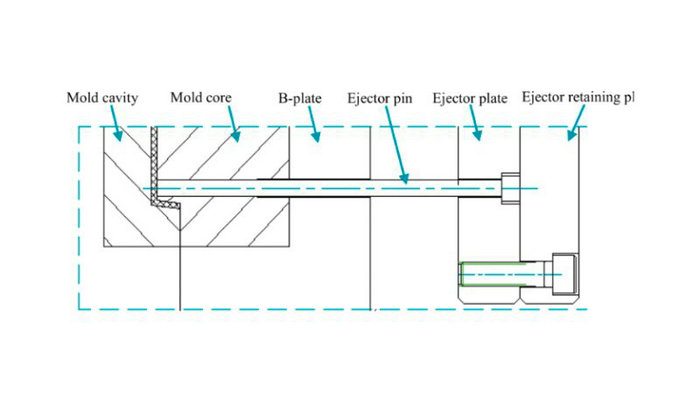
- Ejector Plate Activation: When the mold opens, an ejector plate that holds the ejector pins moves forward.
- Pushing Mechanism: The pins push against the part evenly using a calculated force that’s just enough to eject the part without damage.
- Post-Ejection: The mold closes, and the pins retract to their original position, primed for the next cycle.
Pointers to Remember:
- Equal surface area contact is essential to prevent part distortion.
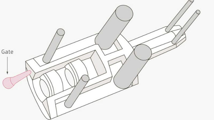
- Post gates can impact the force distribution and must be considered in pin placement.
Optimizing for Efficiency
To keep your cycle time down and the quality up, you’ll focus on:
- Ejection Balance: Distribute the force so that the part exits smoothly without sticking or warping.
- System Maintenance: Regular checks on your ejection system avoid unexpected downtime. Keep an eye on those pins and pads!
Common Issues and Solutions
When it comes to injection molding, ejector pins play a critical role, but issues with pin marks and wear can affect the quality and longevity of both your products and molds. Let’s look at how you can address these common concerns.
Ejector Pin Marks and Surface Defects
Ejector pin marks are those little blemishes you might find on the surface of your plastic parts post-molding. These are often due to pins pushing the part out of the mold. To minimize these unsightly defects, you should:
- Choose the right resin: Some resins, because of their properties, are more prone to showing ejector pin marks than others. Opt for resins that can withstand the ejection process better.
- Rethink gate locations: The position of gates can influence where stress is applied during ejection. By optimizing gate locations, you can reduce the likelihood of pin marks.
- Design adjustments: Small tweaks in your product’s design can make a big difference. Adding draft angles and considering the flow and cooling of the resin could prevent ejector pin marks.
Reducing Wear and Tear
Your ejector pins and molds undergo a lot of stress with each injection cycle. To protect them from wear and tear and keep your operation running smoothly:
- Regular maintenance: Keep an eye on your ejector pins and replace them when they show signs of damage. This not only prevents defects but also extends the life of your mold.
- Material selection: The material of your ejector pins matters. Investing in high-quality, durable pins can withstand the rigors of ejector forces and resist wear.
- Polishing and lubrication: Keep your pins polished and well-lubricated to reduce friction, which can lead to wear and premature damage.
Advanced Concepts in Ejector Pin Design
When you’re looking to optimize your injection molding process, understanding advanced ejector pin design is crucial. The right design advancements can significantly enhance the performance and longevity of your ejector pins, and consequently, your mold’s efficiency.
Use of DLC in Ejector Pins
Diamond-like carbon (DLC) coatings have revolutionized ejector pin design by reducing wear and friction. Imagine a scenario where your ejector pin has to slide through the ejector pin channel smoothly, again and again; DLC coatings ensure your movements are slick with minimal resistance. This is especially beneficial when your pins interface with an edge gate or during the ejection of parts with tight draft angles.
Key Benefits:
- Reduced friction
- Increased resistance to wear
- Compatible with various metals, including nitride H13 ejector pins
Precision and Customization
Customizing ejector pins to the specific needs of your molding project isn’t just about precision—it’s about getting the perfect fit for optimal results. Whether it’s a raised ejector pad for more uniform force distribution or adjusting the runner system for efficient flow, the focus on precision ensures every aspect of your ejector system is tailored to your part design.
- Precision Manufacturing: Ensures perfect alignment within the ejector pin channel, which is vital for smooth operation.
- Customization Options: Include specific considerations for various mold features, such as the design of raised ejector pads or modifying draft angles for easier part release.