Manufacturing and assembly are two of the major steps in modern industrial production; teams often face a choice during product design: focus on how parts are made or how they come together. That is why DFM and DFA are introduced.
This article will not only explain what each method does and make comparison, but also show how to combine DFM and DFA in real manufacturing processes.

What Is Design for Manufacturing (DFM)?
Design for Manufacturing (DFM) is the practice of shaping a design so factories can produce it with standard tools and processes. It looks at how parts move from drawings to finished goods.
DFM also considers the needs of the manufacturing partner. Each factory has different machines, tooling, and skill levels. A design that fits those limits reduces errors, rework, and delays during production.
Core Principles of DFM
DFM principles cover every major step of a production chain, which supports quality control and shortens lead time by avoiding custom setups. They mainly consist of these following steps:
- Align design with process and material
- Use proven manufacturing processes
- Standardize features and components
- Minimize part complexity
- Design for easy tooling and fixturing
- Limit tight tolerances to critical features
- Specify realistic surface finish levels
Benefits and Impact on Product Development
DFM lowers production costs by reducing scrap, rework, and manual labor. Fewer design changes after release save both time and money.
DFM also improves product quality. Parts come out more consistent when the design matches process limits. This consistency supports inspections and repeatable results.
During product development, DFM helps teams make decisions earlier. Clear feedback from a manufacturing partner guides tooling plans and schedules. That early alignment leads to faster ramps, better cost reduction, and fewer surprises in full production.
What Is Design for Assembly (DFA)?
Design for Assembly (DFA) is a method used during assembly design to make product assembly simpler and more repeatable. It looks at how workers or machines place, align, fasten, and inspect parts.
DFA applies to both manual and automated assembly processes. It covers electronics, mechanical products, and mixed systems.
Core Principles of DFA
DFA follows several clear principles that guide assembly design.
- Reduce part count by combining functions where possible. Fewer parts mean fewer assembly steps.
- Use standard components like common fasteners and packages. Standard parts lower handling time and errors.
- Design for one-way assembly so parts cannot be installed backward. This supports error prevention.
- Apply modular design to group related parts into subassemblies. Modules simplify product assembly and testing.
- Keep orientation consistent so similar parts face the same direction.
Benefits and Impact on Assembly Process
DFA has a direct effect on assembly costs and output quality. Faster assembly lowers labor time and reduces rework.
Clear assembly steps improve assembly efficiency in automated lines. Pick-and-place machines, robots, and fixtures work more reliably when spacing and orientation stay consistent.
DFA also improves inspection and testing. Technicians can access test points and joints without removing parts.
DFM vs DFA: Main Differences
DFM and DFA both guide better product design, but they target different parts of the production process. One focuses on how a part gets made, while the other focuses on how parts come together.
Focus Areas and Objectives
DFM centers on ease of manufacturing. It guides designers to shape parts that match real manufacturing capabilities.
DFA focuses on ease of assembly. It aims to reduce part count, simplify handling, and shorten assembly time.
The key difference between DFM and DFA lies in where effort goes. DFM improves how parts are made, while DFA improves how parts fit together. Both affect the full product lifecycle, from early design to mass production.
Key Metrics of Success
DFM success shows up in cost reduction during fabrication. Common metrics include scrap rate, cycle time, tooling cost, and material waste. Strong DFM improves production efficiency by reducing rework and process variation.
DFA success appears in assembly performance. Key measures include assembly time, number of fasteners, labor cost, and error rates. Fewer parts often lead to faster builds and better quality.
Both methods support cost savings, but in different ways. DFM lowers the cost of making each part. DFA lowers the cost of putting parts together. Teams often track both sets of metrics to see the full impact.
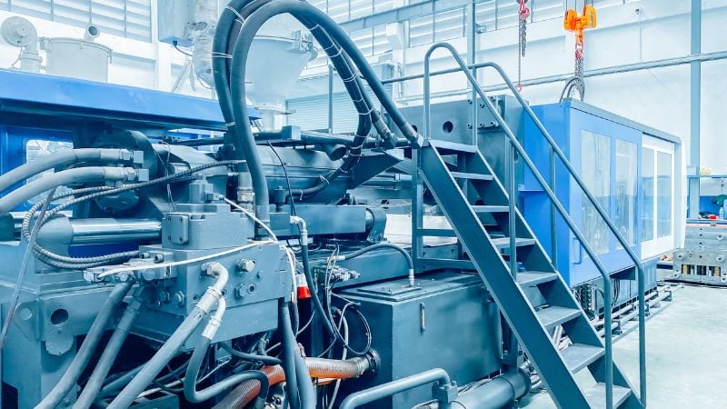
Applications of DFM and DFA in Die Casting and Injection Molding
DFM and DFA shape how parts form, fit, and function in production. In die casting and injection molding, these methods reduce defects, control cost, and support reliable assembly through clear design choices.
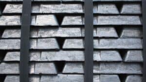
Design for Manufacturability (DFM) in Die Casting
In die casting, DFM focuses on part geometry that supports stable metal flow and solidification. Designers control wall thickness, avoid sharp corners, and add fillets to limit porosity and distortion. Uniform sections reduce internal stress and lower the risk of rework.
Ribs and bosses improve strength without adding excess mass. They also guide metal flow and improve venting. Draft angles allow clean ejection and protect the die from wear.
Surface finish matters in die casting. Smooth transitions reduce sinks and improve coating results. For parts used as heat sinks, DFM supports thermal management by balancing thin walls with enough material for heat transfer.
Close work with manufacturing partners helps confirm tooling limits early. This step prevents costly die changes later.
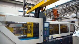
Design for Assembly (DFA) in Injection Molding
In injection molding, DFA reduces assembly time and error. Designers limit part count and combine features where possible. Snap-fits often replace screws to speed assembly and avoid added hardware.
Part orientation matters. Clear assembly direction reduces handling and misalignment. Consistent draft and simple undercuts help parts seat correctly during assembly.
DFA also supports surface finish control. Designers keep cosmetic surfaces away from gates to reduce marks and rework. Textures stay consistent to hide minor defects.
For molded housings that support thermal management, DFA ensures molded features align with metal heat sinks. Proper fit improves heat transfer and avoids stress during fastening.
Component Placement and Standardization in Die Casting, Molding, and CNC
Component placement affects both manufacturing and assembly. Designers place holes, bosses, and inserts with enough spacing to protect tools and molds. Good spacing also improves venting and reduces trapped air.
Standardization lowers cost and risk. Using common fasteners, wall thicknesses, and feature sizes simplifies tooling and inspection. It also reduces setup time across product lines.
Clear placement rules help manufacturing partners plan fixtures and assembly steps. Consistent layouts reduce training needs and limit assembly errors. These choices directly reduce scrap, rework, and production delays.
Integrating DFM and DFA: DFMA in Die Casting and Plastic Injection Molding
DFMA links part design and assembly planning into one process. In die casting and plastic injection molding, this approach lowers cost, improves quality, and reduces late design changes.

Benefits of Combined Implementation
Design teams often combine both into DFMA. This approach balances manufacturing limits with assembly needs. It helps teams avoid late design changes and protect production efficiency.
In die casting, this means controlling wall thickness, draft, ribs, and fillets while also planning how parts locate and fasten during assembly. In plastic injection molding, it means balancing mold flow, shrinkage, and tooling limits with part count and assembly steps.
This combined approach delivers clear results:
- Cost savings from fewer parts, simpler molds, and shorter cycle times
- Quality improvement through uniform walls, stable dimensions, and fewer defects
- Better alignment between functional requirements and real production limits
DFMA helps teams avoid designs that look good on screen but fail in the factory.
Best Practices for DFMA
Effective DFMA starts early and stays practical. Designers should reduce part count first, then shape each part for the chosen process. For die casting, they should avoid thick sections, support bosses with ribs, and use draft angles that match the alloy. For injection molding, they should keep wall thickness uniform and avoid deep or thin features.
Common best practices include:
- Use standard components like fasteners and inserts
- Design parts to self-locate during assembly
- Allow loose tolerances where function permits
- Plan secondary operations only when necessary
Design Reviews and Cross-Functional Collaboration
Strong DFMA depends on structured design review. These reviews should include design, manufacturing, quality, and the manufacturing partner. Each group checks the model against tooling limits, assembly steps, and inspection needs.
Regular reviews reduce rework, protect tooling investment, and keep the design aligned with real production conditions.
Challenges and Optimization Strategies
DFM and DFA often fail when teams ignore small details that drive cost, quality, and build time. The main challenges involve tolerances, process selection, and cost tradeoffs that affect product performance and assembly speed.

Managing Tolerances and Specifications
Tolerances control fit, function, and assembly success, but tight tolerances raise costs fast. CNC machining, for example, becomes slower and more expensive as tolerances shrink. Designers should apply tight tolerances only where function truly depends on them.
Loose tolerances often work for non‑critical features. This choice lowers scrap rates and speeds machining.
Good tolerance practices include:
- Apply tight tolerances only on mating or functional surfaces
- Use standard tolerance ranges supported by the process
- Avoid stacking tolerances across multiple parts
DFA also benefits from tolerance planning. Self-aligning features, chamfers, and lead‑ins reduce the need for precision during assembly. These features lower rework and improve yield.
Selecting Manufacturing Processes
The manufacturing process shapes both part design and assembly effort. A design that suits CNC machining may fail in injection molding due to draft angles, wall thickness, or tool access.
Early process selection prevents redesigns. High‑volume parts often favor injection molding, while low‑volume or complex parts fit CNC machining better.
Key process factors to evaluate:
- Expected production volume
- Material behavior during forming or cutting
- Tooling cost and lead time
Process-aware design supports DFA goals. When parts match the process, teams can minimize part count and reduce secondary operations. Fewer steps mean faster builds and fewer defects.
Balancing Production Costs and Product Performance
Cost reduction should not weaken product performance. Over‑simplified parts may fail under load, heat, or wear. Designers must balance strength, durability, and assembly speed.
Reducing part count often delivers the largest savings. Fewer parts mean fewer fasteners, less handling, and shorter assembly time.
Effective cost-performance tradeoffs include:
- Combining parts without increasing stress risk
- Choosing materials that meet, not exceed, requirements
- Designing features that eliminate fixtures or adjustments
Strong DFM and DFA decisions align cost targets with real use conditions. This balance protects reliability while keeping production efficient.
Conclusion
Integrating Design for Manufacturability (DFM) and Design for Assembly (DFA) into a unified DFMA approach turns product design into a production‑ready strategy rather than a theoretical exercise.
Applied early to die casting, injection molding, and related operations, DFMA reduces redesigns, aligns engineering with real factory limits, and ensures that products not only work in the field but also flow smoothly through the manufacturing line.
FAQ: DFM and DFA in Manufacturing
Can I apply DFM and DFA if my manufacturing process is already chosen?
Yes. Even after a process is selected, DFM can refine geometry, tolerances, and materials to better fit that process, while DFA can simplify part interfaces and assembly steps. You may not achieve all the benefits possible from early DFMA, but you can still reduce rework, assembly time, and defect rates by iterating on the current design.
How do I know if my design has good DFMA?
Look at measurable indicators across both manufacturing and assembly. On the DFM side, low scrap, stable cycle times, and minimal custom tooling changes are positive signs; on the DFA side, reduced part count, short assembly times, and low error or rework rates are key signals. If production ramp‑up is smooth and engineering change requests are limited, your DFMA practices are likely effective.
Who should be involved in DFMA decisions?
DFMA works best with cross‑functional collaboration. Design engineers, manufacturing engineers, quality teams, and key suppliers or manufacturing partners should all review the design together. This ensures that process limits, inspection needs, and assembly methods are considered early, preventing costly late‑stage changes and tooling modifications.


