Plastic molding has come a long way from its first emergence, and has branched into many different processing methods. In this article, we will be focusing on the comparison of two common plastic molding techniques: injection molding and extrusion molding. The following chapters will clarify their differences and features with side-by-side comparisons in different scopes ranging from basic definitions to costs and economic factors.
What’s the Difference: Injection Molding vs Extrusion
- Mechanism and Process
- Equipment and Tooling
- Materials and Part Types
- Design Rules and Part Geometry
- Production Economics and Throughput
- Defects and Troubleshooting
Key Differences in Mechanism and Process
The Plastic Extrusion Process
Plastic extrusion forms long, continuous products by driving molten material through a shaped die. Think of spaghetti leaving a pasta press; the cross‑section is set by the die opening, and the output can, in principle, be endless.
In practice, an extruder’s rotating screw heats, mixes, and pressurizes plastic pellets. The melt is pushed through a die that defines the profile. Then the production line uses air, water baths, or chill rolls to solidify the shape. Pullers control line tension and speed, while cutters, winders, or saws convert the continuous strand into usable lengths or rolls.
The Injection Molding Process
Plastic injection molding makes discrete, fully three-dimensional parts in a repeated cycle. Pellets are plasticized in a heated barrel and then rapidly injected under high pressure into a closed mold. The mold contains one or more cavities that define the part geometry. Runners and gates distribute melt into each cavity. After packing and holding to control shrinkage, cooling solidifies the part. The mold then opens, and ejector pins push the part out, thus completing the cycle.
Key Differences in Equipment and Tooling
Extruder, Dies, and Downstream Handling
An extrusion line includes a hopper and screw/barrel assembly, screen packs and breaker plates for melt filtration, and a die that sets the desired shape.
Downstream equipment stabilizes and converts the product: calibrators and vacuum tanks for dimensional control on hollow profiles, water baths or air knives for cooling, haul‑offs to control line speed, and cutters, slitters, or winders to finish.
Injection Presses, Molds, and Runner Systems
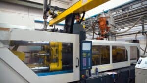
Injection molding cells center on a press rated by clamping force, an injection unit, and a mold tool. The mold is the heart of the manufacturing process: machined cavities and cores, cooling circuits, ejector systems, and sometimes side actions or lifters to create undercuts.
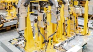
Cold runners are common in simpler molds, and hot runners reduce waste and improve cycle time by maintaining the molten plastic material in the feed system. This process also integrates automation. As an example, some injection molding processes would use robots for part removal, in‑mold labeling, or vision inspection.
Differences Between Injection and Extrusion in Tooling
The most evident difference between extrusion and injection molding toolings is their prices. Under normal circumstances, extrusion dies are faster and cheaper to build. Simple profile dies can be fabricated in days to a few weeks at moderate cost.
Comparatively, injection molds are far more complex. Even straightforward single‑cavity aluminum tools may take several weeks. Not to mention multi‑cavity, tight‑tolerance steel molds, which could require months and significant investment. However, the payback does come with high volumes and repeatable part quality.
Key Differences in Materials and Part Types
Thermoplastics, Thermosets, and Elastomers
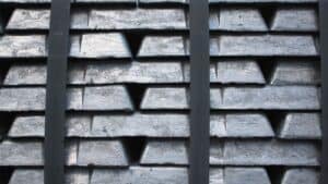
Both processes run thermoplastics such as PP, PE, PVC, ABS, PC, PET, plastic resin, and nylon as their major base materials. However, some materials perform better in one process than another.
Extrusion is often associated with thermoplastics because they melt and resolidify cleanly during continuous processing. Meanwhile, injection molding offers better support to thermoplastics, thermosets like phenolics, epoxies with B‑stage, and elastomers including liquid silicone rubber.
Profiles, Sheets, and Films vs. Discrete Three-Dimensional Shapes
Extrusion specializes in uniform cross‑sections: window frames, cable jacketing, medical tubing, weatherstripping, corrugated sheets, and multilayer films. Co‑extrusion can layer materials to combine barrier properties, stiffness, or color.
Injection molding creates discrete components: bottle caps, enclosures, gears, connectors, toys, lens housings, and structural brackets, automotive parts. It’s the better fit when parts require bosses, living hinges, snaps, threads, or fine textures, all features molded in one cycle rather than added later.
Key Differences in Design Rules and Part Geometry
Wall Thickness and Undercuts
In extrusion, the wall thickness should remain as uniform as the profile allows to avoid differential cooling and warpage. Sharp transitions are discouraged, as radii and balanced flow paths reduce die lines and distortion.
Because the shape is defined by the die opening, true undercuts in the extrusion direction are not possible without post‑forming. Bends or secondary forming can adjust the path after cooling, but the cross-section remains constant.
Injection molding thrives on 3D detail, and could form undercuts using side actions, collapsible cores, or lifters. However, uniform nominal wall thickness is still desirable because it helps minimize sink and warpage, and ribs and gussets are used to stiffen without adding mass.
Tolerances, Surface Finish, and Integrated Features
Extrusion provides moderate tolerances depending on line stability, cooling, and die design. The feed motion of the extrusion method boosts the longitudinal accuracy over distance, but it also brings extra difficulties in small features or tight hole sizes. The finish reflects die quality, cooling, and post‑processing, like embossing rolls for patterns on films and sheets.
Injection molding routinely achieves tighter tolerances and high‑quality finishes right out of the tool. This precision enables features such as mold texturing, polished surfaces, and micro‑features on products like medical devices. Threads, snaps, living hinges, and inserts can be integrated directly into the molded geometry, which minimizes assembly.
Assemblies and Secondary Operations
Extruded outputs often require a series of operations to achieve their final state: cutting, drilling, punching, welding, heat‑bending, or adhesive bonding. For example, an extruded aluminum‑look PVC frame might be cut and mitered, then mechanically joined.
In contrast, injection molding can consolidate multiple functions into one part, like having cable strain reliefs, seals, and fastener bosses molded together. Plastic product may need only gate trimming or deflashing. Overmolding and insert molding further reduce downstream assembly by combining materials or adding metal inserts at the press.
Key Differences in Production Economics and Throughput
Cycle Time and Line Speed
Extrusion operates continuously and its line speed can be tuned to a certain value. Once dialed in, it can produce thousands of meters of product per shift.
The measurement for injection molding is “cycle”: its time can be seconds for simple plastic products like tiny caps or connectors, and tens of seconds to minutes for thicker, larger parts. Multi‑cavity molds multiply output per cycle by the amount of cavities they have, which further increases the production volume.
Scrap, Yield, and Changeovers
Extrusion typically has a low scrap rate after startup, with waste limited to purging, start/end cuts, and off‑spec during changeovers. Co‑extrusion can complicate purging and color changes, but steady‑state yield is still high.
Injection molding scrap can arise from cold runners residues and botched plastic parts with defects. Hot runner systems reduce runner waste and improve consistency but increase tooling cost and maintenance.
Changeovers are generally faster in extrusion (swap die, adjust conditions) than in injection molding (swap mold, revalidate process), especially for complex multi‑cavity tools.
Cost Structure and Breakeven Volumes
Extrusion’s cost structure favors long runs of simple cross‑sections: modest tooling, high material throughput, and minimal labor. It shines for high‑volume, low‑complexity profiles and films where every additional meter lowers unit cost.
Injection molding carries higher fixed costs (tooling, validation) but scales efficiently with volume. Once the mold is amortized, small parts in multi‑cavity tools can be extremely economical.
Key Differences in Defects and Troubleshooting
Common Extrusion Defects and Solutions
Die Lines & Sharkskin
- Causes: Worn or dirty die; excessive shear stress.
- Solutions: Clean/maintain die; adjust process temperatures and screw speed.
Warpage/Bow & Inconsistent Wall Thickness
- Causes: Imbalanced cooling; incorrect puller tension; uneven material flow.
- Solutions: Balance cooling system; calibrate haul-off speed/puller tension; review die design.
Besides these solutions, there are also prevention methods that can reduce the chances of defects altogether. For example, onsite workers should regularly inspect and replace screen packs, and warehouse managers need to ensure material is completely dry, especially for hygroscopic resins like nylon.
Common Injection Molding Defects and Solutions
- Sink Marks: Caused by thick sections, they are resolved by designing uniform walls, using core-outs, and optimizing packing pressure.
- Warpage/Shrinkage: Results from uneven cooling or fiber orientation, and is corrected by improving the mold cooling layout and adjusting gate placement.
- Flash & Short Shots: Flash indicates excessive pressure or clamp force, while short shots point to insufficient fill, venting, or low melt temperature; both require balancing process settings and ensuring proper venting.
- Burn Marks & Splay: Traced to trapped air or moisture, these are eliminated by improving mold venting and thoroughly pre-drying the material.
A methodical approach adjusting temperatures, speeds, pressures, and venting, combined with regular mold maintenance, typically resolves these issues.
Process Control, Metrology, and Validation
Both processes benefit from disciplined control, but injection molding generally runs to tighter windows and tolerances. Scientific molding practices, design of experiments (DOE), cavity pressure sensing, decoupled fill/pack, and real‑time monitoring are common.
Extrusion relies on stable melt temperature, pressure, and line speed, plus SPC charts for critical dimensions. Metrology ranges from calipers and optical comparators on the floor to CMM and CT scanning for complex molded parts. Validations are more formalized in regulated industries, where traceability and process capability must be demonstrated.
How to Select Between Extrusion and Injection Molding
Making use of the knowledge you learned from this article, you can analyze the situations in a practical way by mapping needs across these four dimensions.
Geometry:
- Constant cross‑section → extrusion.
- Complex 3D with undercuts → injection molding.
Tolerances and finish:
- Moderate tolerances and functional finish → extrusion.
- Tight tolerances and cosmetic surfaces → injection molding.
Volume and speed:
- Very long lengths or continuous rolls → extrusion.
- High part counts of discrete items (especially with multi‑cavity tools) → injection molding.
Tooling and time‑to‑market:
- Need fast, inexpensive tooling → extrusion.
- Willing to invest for precision and features → injection molding.
When in doubt, prototype early, involve manufacturing engineers in DFM reviews, and run a quick breakeven analysis comparing die cost and line speed to mold cost, cavities, and cycle time.
Conclusion
Ultimately, the differences between injection molding and extrusion are closer to traits rather than advantages and disadvantages, and the choice between them is about which process fits the job at hand better. Your decision should be fundamentally guided by the geometry of your final product. Beyond this, you should also pay more attention to budget, timeline, and volume. Only then can you confidently select the manufacturing process when navigating the plastic manufacturing industry for molding services.
Frequently Asked Questions
How does material selection for one process differ from the other in terms of additives?
While both processes use the same base thermoplastics, the formulation (additives like colorants, UV stabilizers, or lubricants) can differ. Extrusion compounds might be optimized for superior thermal stability to withstand the continuous heat history in the barrel. Injection molding grades may be formulated for faster flow rates to fill thin walls and complex molds quickly.
Are there any part geometries that fall into a “gray area” between the two processes?
Yes, certain parts can be challenging. A long, straight part with a constant cross-section but small, complex undercuts might be extruded and then put through a secondary forming process, or it might be more cost-effective to injection mold it in multiple sections. Similarly, a very large, flat part could potentially be made by extrusion (as a sheet) or by large-scale injection molding, requiring a detailed cost-benefit analysis.


