The largest amount of plastic injection mold that may be injected during a molding cycle is known as the shot size. Pellets are fed into the barrel and screw assembly through the hopper.
Using the injection molding technique, molten material is injected into the mold’s cavity to create large quantities of plastic parts.
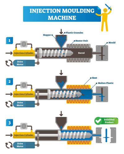
In the process of plastic injection molding, the raw material is introduced into the barrel, melts, and plastic is then injected into the cavity of the mold for cooling and solidification after the mould is closed. Finally, the mold opens, and the components are expelled.
How To Calculate The Shot Size
The duration of residence times is influenced by the size of the shot and barrel, which may also impact the final product’s quality. Long residence durations and polymer degradation may come from small shot sizes that require little barrel capacity.
Small shot sizes that occupy less than 20% of the barrel’s capacity frequently result in extended residence times, which in turn cause polymer degradation and inadequate process control.
On the other hand, big shot sizes and barrel fill levels greater than 50% may cause uneven melting and slow screw recovery.
Additionally, larger screws typically have lower plastic pressure capabilities. Large shot sizes, which occupy more than 65% of the barrel’s capacity, frequently cause melt-quality problems, such as unmelt, poor melt uniformity, and long screw recovery times.
To be safe, you can consider placing a two-barrel order. Even more, molds can be used with two barrels. When you order a second barrel with the new machine, you can be pleasantly pleased by its inexpensive cost. Barrels can be switched in under 30 minutes with the right specifications and an experienced operator, even if the barrel is hot.
Formula For Mold Shot Size In Injection Molding
The simplest formula for calculating the mold shot size is:
Shrinkage + Spruce volume +Product volume + Runner volume = Mold shot size
Formula Machine Shot Capacity/ Shot Size
The total weight or volume that the screw injects during one molding cycle is expressed as machine shot capacity (g)/machine shot size (mm), also known as the machine injection capacity.
Your calculations when considering pressure should be as follows:
Stroke X Screw piston surface = injection volume
Injection force/ screw piston surface = injection pressure
Therefore:
Maximum injection volume per cubic unit X maximum injection pressure (bar per cubic unit)/1000 = shot capacity of the injection unit.
Calculations when using screw weight and material density should be as follows:
Mass/density= volume
ᴨ*D2*Shot size/4= Barrel/Shot volume
Factors That Affect Product Shot Size
There are several factors that you must consider when calculating a shot size. These factors are as follows:
- You must consider spruce volume, runner volume, and product volume while determining the shot size. This is because the polymer must fill the spruce, runner, and product volume when injected into the mold.
- Another important issue that affects the calculations for shot size is polymer shrinkage. Shrinkage results from cooling the melt polymer. Due to the varied densities of polymers, mold shrinkage varies.
- A polymer’s kind and quantity of additives can change its density and flow characteristics.
These factors can help you estimate the shot size, volume and barrel capacity.
Injection Unit
The purpose of the injection unit is to melt the plastic material uniformly before injecting it into the mold at a predetermined pressure and flow rate. These are demanding activities because fluoropolymers have limited thermal conductivity, a high specific heat, and high melt viscosity.
Again, numerous variations have been developed to address the complex issues at hand. A general classification of the variations can be made into four primary injection unit concepts:
- Single-stage plunger or ram
- Dual-stage ram
- Screw with one stage
- Screw/ram with two stages
Although it still exists in tiny machines and some specialized equipment, the single-stage ram unit is essentially obsolete due to its ineffectiveness in heating, mixing, and pressure transmission. It benefits from simplicity and affordability.
Additionally, the two-stage ram is all but obsolete. The ram is still an ineffective mixer and heater despite an attempt to enhance it by separating the heating and pressure flow operations.
The two-stage screw/ram unit further separates the roles of flow and heat by using a ram for injection instead of a screw for mixing and heating. The idea is appealing because both are effective tools for their respective tasks.
Further, the injection unit is often rated using the maximal injection pressure and available injection volume. The greatest possible pressure at the screw’s downstream end is called the injection pressure. This depends on the screw’s diameter and the force pushing against it.
However, ensure that you don’t confuse it with the pressure in the hydraulic line acting on the injection cylinder, which drives the screw, nor should it be interpreted as the pressure required to fill the mold cavities. Due to pressure losses in the nozzle and mold feed systems, this is substantially less.
The injection unit’s main series of actions is as follows:
- The material is heated and melted as the screw turns, then transported along the screw flights to the downstream end of the screw. The barrel nozzle is closed by using a mechanical or thermal valve or by the existence of an earlier molding.
Up until enough melt has accumulated to manufacture the next molding, the collecting melt forces the still-rotating screw back against a controlled resistance (the back pressure). The rotation of the screw halts here. It’s time to be ready for the melt.
- When the barrel nozzle is opened, the screw moves forward in an axial direction without rotating, acting like a ram. As a result, the melt gathered in front of the screw’s downstream end is forced (injected) through the nozzle and into the mold.
To stop melt from flowing back down the screw flights, a valve system may be installed at the screw’s downstream end. This is the injection or mold-filling stage.
- After the mold has been filled, the screw pressure is kept for a short while to make up for the cooling melt’s volumetric shrinkage inside the mold. The packing or holding phase is now.
- Finally, it gets to the holding phase, where the injection unit cycle resumes with screw rotation and melts preparation while the mold is kept closed to allow the molding to cool to the ejection temperature.
There are significant pressure drops when the plastic melt is forced into the injection nozzle and subsequently through the mold feed system and cavities. Simple rules cannot be used to calculate these pressure losses.
Clamping Unit
Mold closure is maintained against forces created when plastic is pushed into a closed mold by injection pressure using a clamping unit for an IMM. It has a drive system that can move the injection molding machine’s moving platen in at least one direction.
Types Of Clamping Units
There are several types of clamping units in the injection molding process. They are as follows:
Toggle Type Clamping
A mechanical device that amplifies force is a toggle. Two bars are connected and end with a pivot in a molding machine. One bar’s end is connected to a fixed platen, while the other is connected to a mobile platen. The toggle has a V-shaped shape when the mould is opened. The two bars form a straight line when pressure is applied to the pivot.
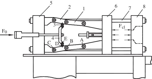
The benefits of toggle type clamping include that it requires less money and horsepower to be done and provides a positive plan of the mold. Further, the setbacks of the toggle type clamping are that it requires high maintenance and is difficult to do.
Hydraulic Clamping
In this instance, the RAM of the hydraulic system is tied to the moving platen, and a clamping unit powered by a hydraulic cylinder is directly connected to the closed moving mold. The hydraulic cylinder has two sections: the oil input and the exit.
Oil pushes the RAM forward when it enters the cylinder under pressure, causing the moving platen and mold to shut. Additionally, the RAM comeback and mold are open when oil is released from the cylinder.
Some advantages of hydraulic clamping include easy control of clamp speed and support at any angle, simple measurement of clamping force, easy mode setup and clamp force adjustment, and its simplicity in maintenance.
The drawbacks to this type of clamping are that it costs more and is more expensive than a toggle system and a positive noun clamp.
Magnetic Type Clamping Unit
Magnetic modules inside the magnetic mold clamping plates or platens produce the clamping force. The interface panel can control mold clamping, mold changing, and magnetizing and demagnetizing the platens.
This clamping unit’s benefits include electricity only being required during the magnetization and demagnetization phases, not while clamping, real-time clamp force measurement with many safety features and free maintenance.
Mold Shot Weight
The amount of material injected into the mold to fill the mold, including the feed system, is known as the “mold shot weight” or “product shot weight.” Spruce, runner, and gate weight are the components of shot weight, on the other hand. The distance the screw covers to fill the product, including the feed system, is known as the mold/product shot size.
Conclusion
Using the injection molding technique, raw plastic is melted, injected into the mold, allowed to cool and solidify, and then the finished object is expelled. The shot size is crucial because it prevents polymer underfill and flash. Other factors, such as the barrel capacity, also affect the general injection molding process.


