Casting inspection, as its name implies, is the process of finding surface, internal, and dimensional defects so cast parts perform safely as designed.
Here in this article, we will focus on the inspection of die casting parts and build a clear path from core inspection basics to specialized uses and common questions.
Three Fundamental Steps of Metal Casting Inspection
Casting inspection protects casting soundness and supports quality assurance across production and prevents failures caused by various defects.
[For a full breakdown of defect types and their root causes, refer to our dedicated Casting Defects Guide.]
The tasks of inspection occur at several points in the process and can be allocated into three stages, with each targeting different risks and catching problems before they move downstream or are delivered to customers.
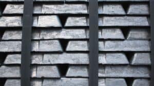
- Incoming material checks: Verify alloy chemistry and charge quality.
- In‑process inspection: Monitor molds, cores, and pouring conditions.
- Post‑casting inspection: Check dimensions, surfaces, and internal quality.
In the following chapter, we will be detailing these die casting related inspection and testing methods by their features and give you an example of how a die-casted part is inspected.
Non-Destructive Testing (NDT) Methods in Die Casting
Non-destructive testing, or NDT, checks casting quality without cutting or breaking the part. Inspectors use these methods to detect cracks, porosity, and inclusions that can weaken performance.
Manufacturers often combine several NDT methods because each one finds different defect types. Some methods work best on surfaces, while others support volumetric inspection of internal features.
Common NDT methods for castings include visual inspection, ultrasonic testing (UT), and radiographic testing (RT). The choice depends on casting size, material, and quality requirements.
Visual Inspection Techniques
Visual inspection is the first step in most casting inspections. Inspectors look for visible defects by direct viewing, magnification, or simple tools like mirrors and borescopes.
Visual inspection works best for surface defects but cannot detect internal cracks or subsurface blowholes. Despite this limit, it remains valuable because it is fast, low cost, and easy to perform.
Radiographic Testing and Digital Radiography
Radiographic testing (RT) uses x-ray inspection to see inside a casting. Traditional radiography creates radiographic films, while digital radiography produces electronic images.
RT excels at providing clear views of internal structure and supports reliable volumetric inspection. Advanced options include CT inspection, which builds a 3D image of the casting. Some systems also combine radiography with x-ray fluorescence for material checks.
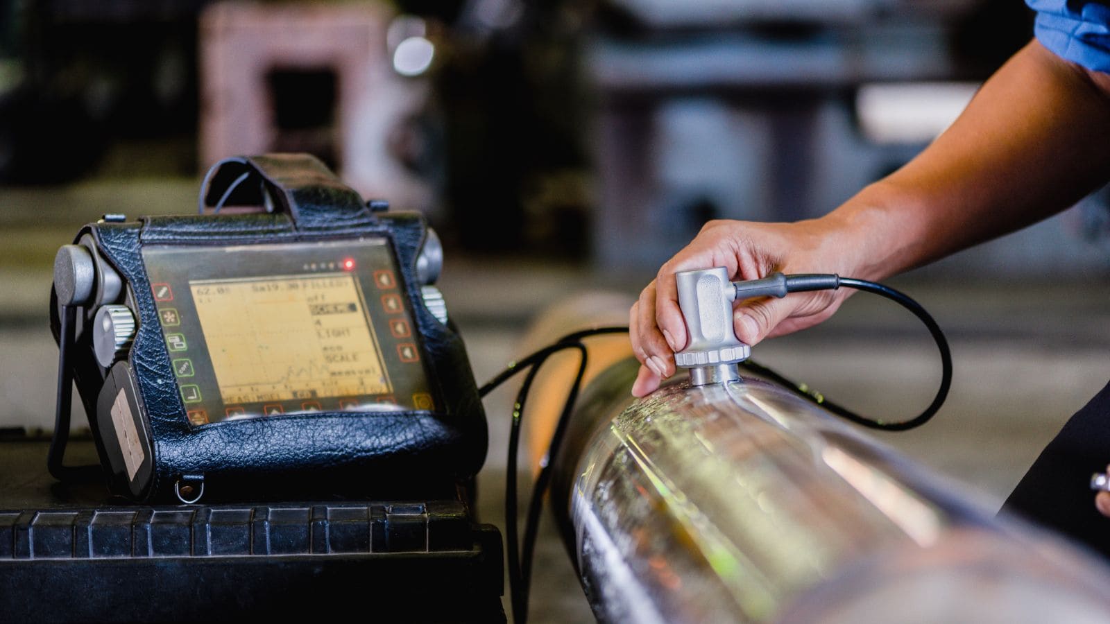
Ultrasonic Testing
Ultrasonic testing (UT) uses high-frequency ultrasound to find internal defects. The inspector sends sound into the casting and measures reflected signals. It works well on thick sections and dense metals where x-ray access may be limited. Therefore, many foundries use UT for critical load-bearing castings.
However, this method requires trained technicians and proper calibration of testing equipment, and UT often does not detect surface defects well, which again emphasizes the importance of a combined approach.
Dimensional and Geometric Inspection
Dimensional and geometric inspection checks whether a casting matches the required size, shape, and tolerance. It focuses on measuring features that affect fit, function, and later machining steps.
Dimensional Inspection Methods
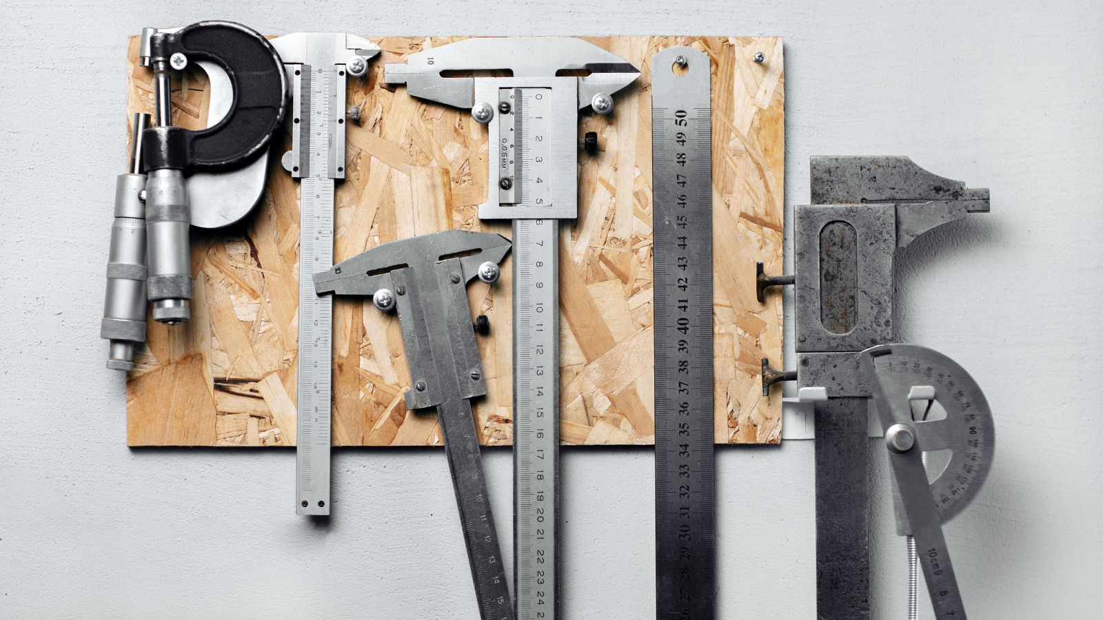
Dimensional inspection measures key features such as length, thickness, hole size, and angles. Inspectors compare results to drawing limits and tolerance values.
Common inspection equipment includes calipers, micrometers, height gauges, and go/no-go gauges. These tools work well for simple features and quick checks on the shop floor.
For complex castings, inspectors use fixtures and surface plates to control part position. Proper setup matters because poor alignment can cause false results. Clean surfaces and stable temperature also improve measurement reliability.
Typical checks include:
- Overall length and width
- Hole diameter and location
- Wall thickness and flatness
- Parallelism and perpendicularity
Coordinate Measuring Machine (CMM) Applications
A coordinate measuring machine, or CMM, measures casting geometry in three dimensions. It uses a probe to collect точные point data from the part surface.
CMM systems inspect complex shapes that manual tools cannot measure well. They verify true position, profile, flatness, and other geometric tolerances. This capability supports parts with tight fit or mating requirements.
Many CMMs import CAD models to compare actual results to nominal geometry. The system then reports deviation values in clear numeric form. This process helps identify pattern shift, mold wear, and machining allowance issues.
CMM inspection works best in controlled environments. Stable temperature and proper fixturing reduce measurement variation and improve repeatability.
Dimensional Analysis and Accuracy
Dimensional analysis reviews inspection data to confirm the casting meets design intent. It looks beyond single measurements and checks trends across multiple features or parts.
Accuracy depends on several factors:
- Tool calibration and resolution
- Operator technique and setup
- Casting surface condition
- Environmental control, especially temperature
Inspectors document results using inspection reports or digital systems. These records support traceability and process control.
When results approach tolerance limits, dimensional analysis helps decide if the casting remains usable or needs correction. This step protects downstream machining and final assembly from costly errors.
Material Verification and Performance Testing
While dimensional and NDT methods confirm a part’s geometry and structural soundness, they do not verify the quality of the material itself. To bridge this gap, inspectors turn to other inspection methods that analyze the raw chemistry and mechanical properties of the metal.

Chemical Composition Examination
Chemical composition analysis checks that a casting matches alloy specifications. Labs measure key elements like carbon, silicon, chromium, or nickel using tools such as spectroscopy or X‑ray fluorescence. These tests find errors that visual inspection cannot detect.
Small changes in chemistry can lower strength, reduce wear resistance, or cause cracking. For this reason, inspectors compare results to defined limits, not target values alone. Many shops test samples from each heat to control variation.
Chemical analysis confirms the alloy meets specifications. Deviations from these specs can then be correlated with known defect mechanisms identified during inspection. These tests do not damage the part and support consistent process control.
Hardness and Impact Testing
Hardness testing checks resistance to surface indentation and wear. Common methods include the Brinell hardness test and Rockwell hardness testing. Brinell hardness works well for rough or coarse-grain castings, while Rockwell suits faster shop checks.
Hardness numbers link closely to alloy composition and heat treatment. Many hardness tests cause minimal damage, but they still fall under mechanical properties testing. Impact testing goes further by striking a notched sample to measure energy absorbed during fracture.
Impact testing reveals how a casting behaves under sudden loads. This data matters for parts exposed to shock, vibration, or low temperatures.
Service Load and Pressure Testing
Service load testing applies real or simulated loads to confirm performance in use. Load testing may involve static weight, cyclic force, or combined stresses. This method checks stiffness, deformation, and failure points under controlled conditions.
Pressure testing is common for castings that carry fluids or gases. The part is sealed and pressurized to detect leaks or ruptures.
Service load testing supports final approval for safety-critical parts. It helps confirm that the casting will perform as designed under actual operating conditions.
An Example of Die Casting Inspection
Frequently Asked Questions
How do manufacturers decide which NDT method is right for my parts?
The choice depends on the material, the criticality of the part, and the likely defects. For example, safety-critical components like steering knuckles often require ultrasonic or X-ray inspection to guarantee internal soundness.
For high-volume, non-structural parts, visual inspection and dimensional checks are usually sufficient. The decision is based on a risk assessment of where and how the part might fail.
How does the inspection of a prototype die casting differ from a production part?
Prototype inspection focuses on validation and process development, so it is typically more intensive, often involving CT scanning and detailed dimensional analysis. Production inspection shifts toward efficiency and speed, using techniques like go/no-go gauges and sampling plans to quickly verify that the now-stable process continues to produce good parts.


