Injection molding tolerances define the permissible limits of dimensional variation in molded parts. Understanding and managing these tolerances is crucial for ensuring that parts meet design specifications and function as intended.
In this comprehensive guide, we will explore the factors that influence tolerances, the importance of maintaining precise tolerances, and strategies for optimizing them to achieve flawless plastic components.
Whether you’re a designer, engineer, or manufacturer, this article will equip you with the knowledge needed to navigate the complexities of the injection molding process and enhance the quality and reliability of your products.
What is Injection Molding Tolerances?
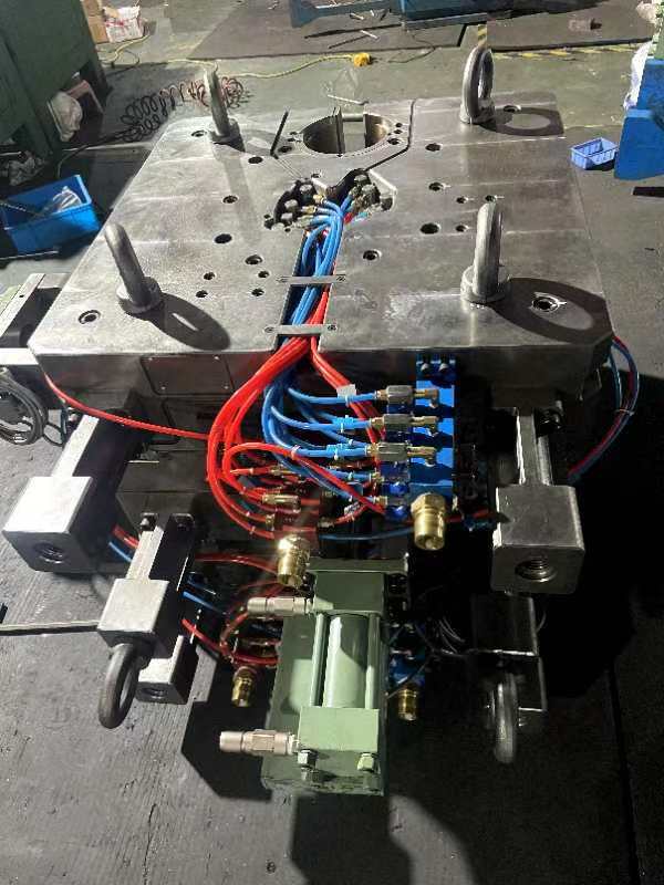
Plastic injection molding tolerances are expressed as plus or minus (±) values in millimeters or inches that specify the acceptable deviation from the nominal dimensions of a part. They are crucial for ensuring parts fit and function properly, especially when assembling multiple components.
There are two types of tolerance: machining tolerance and resin tolerance.
Machining tolerance refers to the tolerance built into the mold tool itself. Typically, injection molds are CNC machined to tolerances of +/- 0.003 inches (0.076 mm). This represents the precision of the mold cavity dimensions.
Resin tolerance refers to the tolerance of the finished molded part, which is influenced by the material properties and molding process. The resin tolerance is generally greater than or equal to +/- 0.002 inches per inch (0.051 mm per mm).
Together, these two types of tolerances determine the overall dimensional accuracy achievable for injection molded parts.
The actual achievable tolerances can vary based on different factors. However, in general, for non-critical applications, the typical tolerance rate is ±0.1 mm; for applications requiring tighter tolerances (e.g., medical parts) is ±0.025 or better.
Why are Injection Molding Tolerances Important?
Many industries, such as automotive, aerospace, and medical devices, have strict tolerance requirements for safety and regulatory compliance.
Tolerances determine whether parts will fit together correctly during assembly and function as intended. Even small deviations can cause issues with fit, alignment, and performance, especially for complex assemblies.
What Affects the Injection Molding Tolerances?
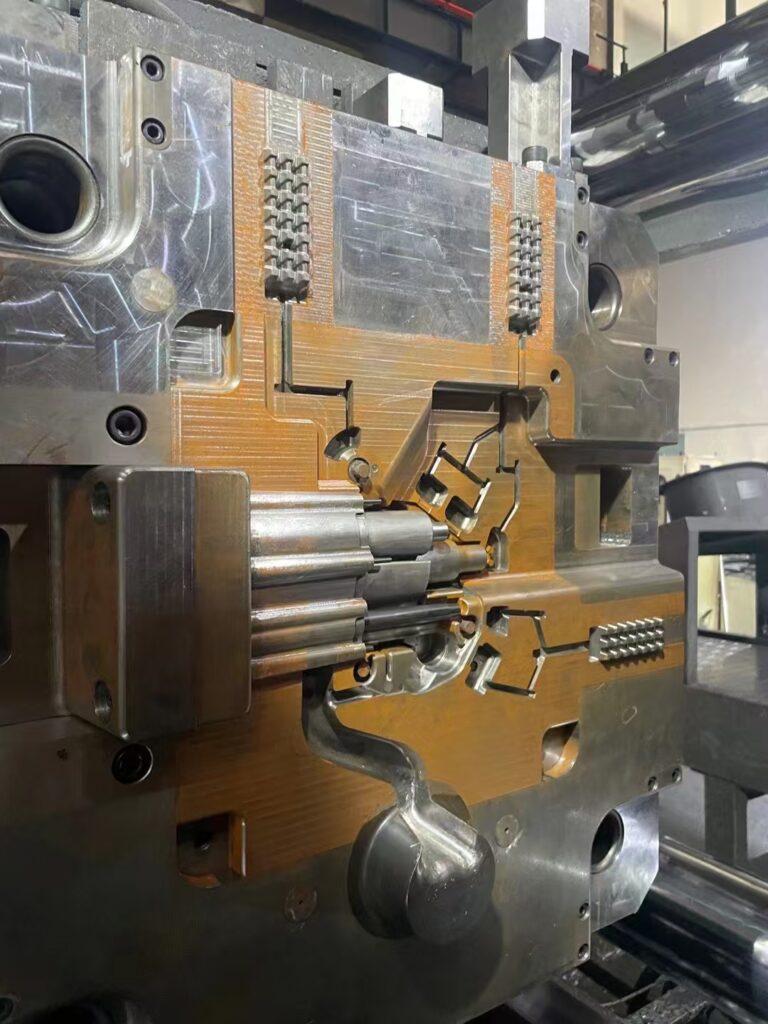
Injection molding tolerances are influenced by several factors, which can affect the dimensional accuracy and consistency of molded parts. Here are the main factors based:
- Shrinkage: Different materials have different shrinkage rates, which impact the ability to achieve tight tolerances. Crystalline materials generally have higher shrinkage rates compared to amorphous materials due to phase changes during cooling. This affects the volume and dimensions of the final part.
- Warpage: As the resin cools in the mold, all parts experience shrinkage. Parts with a uniform wall thickness tend to shrink evenly, which helps prevent warping and sink marks. In contrast, parts with non-uniform wall thicknesses cool and shrink at varying rates, leading to an increased likelihood of warping due to the design.
- Thermal Expansion: Plastics generally exhibit high thermal expansion rates, which can cause dimensional changes when temperatures fluctuate. This is especially crucial when parts are used in environments with temperature variations or are combined with materials such as metals.
- Part Design: The geometry, size, and wall thickness of a part significantly influence tolerance control. Larger parts or those with thick sections may experience different shrink rates, making it more challenging to maintain tight tolerances. Uniform wall thickness and strategic design features can help manage these issues.
- Part Complexity: Complex parts can affect the material flow and tooling design, impacting the ability to maintain tight tolerances. Proper management of injection pressure, resin viscosity, and mold fill time is essential to ensure consistent part quality.
- Tooling: The design and material of the mold, as well as the number of cavities, affect the ability to achieve desired tolerances. Consistent cooling and heating are crucial for maintaining tight tolerances. Multi-cavity or family tools require careful design and support to avoid errors due to pressure or temperature variations.
How to Reduce the Impact of Factors Affecting Injection Molding Tolerances
To reduce the impact of factors affecting injection molding tolerances, several strategies can be employed:
- Design for Manufacturability (DFM):
- Engage in DFM practices early in the mold design process to anticipate potential variances and avoid costly redesigns. This involves designing parts with consistent wall thicknesses and appropriate draft angles and considering the placement of features like bosses and ribs to minimize warpage and shrinkage.
- Material Selection:
- Choose materials with suitable shrinkage rates for the application. Consider the thermal expansion properties and how different materials might interact, especially in multi-material assemblies. Oversize the mold dimensions to account for material shrinkage.
- Tooling Considerations:
- Design molds with precise tooling to ensure consistent plastic part dimensions. This includes optimizing gate locations for even material flow, using cooling channels for uniform cooling, and placing ejector pins to minimize warping and surface defects.
- Process Control:
- Implement effective process controls to manage variables such as temperature, pressure, and cooling time. Use sensors to monitor these parameters in real time, allowing for rapid adjustments to maintain consistent tolerances.
- Rapid Prototyping and Testing:
- Utilize rapid prototyping to test and refine designs before full-scale production. This allows for adjustments to be made to the design or process to improve tolerances and part quality.
The Injection Molding Tolerances Standards

Here is a table visualizing the dimensional tolerances in millimeters (mm):
| Material | Dimension Range | Commercial Tolerance | Precision Tolerance |
| ABS | 1 to 20 | ±0.100 | ±0.050 |
| 21 to 100 | ±0.150 | ±0.100 | |
| 101 to 160 | ±0.325 | ±0.100 | |
| ABS/PC Blend | 1 to 20 | ±0.100 | ±0.050 |
| 21 to 100 | ±0.150 | ±0.100 | |
| GPS | 1 to 20 | ±0.075 | ±0.050 |
| 21 to 100 | ±0.150 | ±0.080 | |
| HDPE | 1 to 20 | ±0.125 | ±0.075 |
| 21 to 100 | ±0.170 | ±0.110 | |
| LDPE | 1 to 20 | ±0.125 | ±0.075 |
| 21 to 100 | ±0.170 | ±0.110 | |
| Mod PPO/PPE | 1 to 20 | ±0.100 | ±0.050 |
| 21 to 100 | ±0.150 | ±0.100 | |
| PA | 1 to 20 | ±0.075 | ±0.030 |
| 21 to 100 | ±0.160 | ±0.130 | |
| PA 30% GF | 1 to 20 | ±0.060 | ±0.030 |
| 21 to 100 | ±0.120 | ±0.100 | |
| PBT 30% GF | 1 to 20 | ±0.060 | ±0.030 |
| 21 to 100 | ±0.120 | ±0.100 | |
| PC | 1 to 20 | ±0.060 | ±0.030 |
| 21 to 100 | ±0.120 | ±0.100 | |
| PC 20% Glass | 1 to 20 | ±0.050 | ±0.030 |
| 21 to 100 | ±0.100 | ±0.080 | |
| PMMA | 1 to 20 | ±0.075 | ±0.050 |
| 21 to 100 | ±0.120 | ±0.070 | |
| POM | 1 to 20 | ±0.075 | ±0.030 |
| 21 to 100 | ±0.160 | ±0.130 | |
| PP, 20% Talc | 1 to 20 | ±0.100 | ±0.050 |
| 21 to 100 | ±0.120 | ±0.100 | |
| PPO/PPE | 1 to 20 | ±0.080 | ±0.050 |
| 21 to 100 | ±0.100 | ±0.080 | |
| PPS, 30% GF | 1 to 20 | ±0.050 | ±0.050 |
| 21 to 100 | ±0.080 | ±0.080 | |
| SAN | 1 to 20 | ±0.080 | ±0.050 |
| 21 to 100 | ±0.100 | ±0.080 |
The following table visualizes the dimensions of Concentricity/Ovality Tolerances (in mm)
| Material | Dimension Range | Commercial Tolerance | Precision Tolerance |
| ABS | up to 100 | ±0.230 | ±0.130 |
| ABS/PC Blend | up to 100 | ±0.230 | ±0.130 |
| GPS | up to 100 | ±0.250 | ±0.150 |
| HDPE | up to 100 | ±0.250 | ±0.150 |
| LDPE | up to 100 | ±0.250 | ±0.150 |
| PA | up to 100 | ±0.250 | ±0.150 |
| PA, 30% GF | up to 100 | ±0.150 | ±0.100 |
| PBT, 30% GF | up to 100 | ±0.150 | ±0.100 |
| PC | up to 100 | ±0.130 | ±0.080 |
| PC, 20% GF | up to 100 | ±0.130 | ±0.080 |
| PMMA | up to 100 | ±0.250 | ±0.150 |
| POM | up to 100 | ±0.250 | ±0.150 |
| PP | up to 100 | ±0.250 | ±0.150 |
| PP, 20% Talc | up to 100 | ±0.250 | ±0.150 |
| PPO/PPE | up to 100 | ±0.230 | ±0.130 |
| PPS, 30% GF | up to 100 | ±0.130 | ±0.080 |
| SAN | up to 100 | ±0.230 | ±0.130 |
Straightness/Flatness Tolerances (mm)
| Material | Feature Size | Commercial Tolerance | Fine Tolerance |
| ABS | 0–100 mm | ±0.380 | ±0.250 |
| 101–160 mm | ±0.800 | ±0.500 | |
| ABS/PC Blend | 0–100 mm | ±0.380 | ±0.250 |
| 101–160 mm | ±0.800 | ±0.500 | |
| PA | 0–100 mm | ±0.300 | ±0.150 |
| 101–160 mm | ±0.500 | ±0.250 | |
| PA GF 30% | 0–100 mm | ±0.150 | ±0.080 |
| 101–160 mm | ±0.200 | ±0.100 | |
| POM | 0–100 mm | ±0.300 | ±0.150 |
| 101–160 mm | ±0.500 | ±0.250 | |
| PP | 0–100 mm | ±0.850 | ±0.500 |
| 101–160 mm | ±1.500 | ±0.850 | |
| SAN | 0–100 mm | ±0.380 | ±0.250 |
| 101–160 mm | ±0.800 | ±0.500 |
Blind Hole Depths Tolerances (mm)
| Material | Depth Range | Commercial Tolerance | Fine Tolerance |
| ABS | up to 100 mm | ±0.200 | ±0.100 |
| ABS/PC Blend | up to 100 mm | ±0.200 | ±0.100 |
| PA | up to 100 mm | ±0.150 | ±0.080 |
| PA GF 30% | up to 100 mm | ±0.100 | ±0.050 |
| POM | up to 100 mm | ±0.150 | ±0.080 |
| PP | up to 100 mm | ±0.250 | ±0.150 |
| SAN | up to 100 mm | ±0.200 | ±0.100 |
Hole Diameter Tolerances (mm)
| Material | Diameter Range | Commercial Tolerance | Fine Tolerance |
| ABS | up to 100 mm | ±0.100 | ±0.050 |
| ABS/PC Blend | up to 100 mm | ±0.100 | ±0.050 |
| PA | up to 100 mm | ±0.080 | ±0.040 |
| PA GF 30% | up to 100 mm | ±0.050 | ±0.025 |
| POM | up to 100 mm | ±0.080 | ±0.040 |
| PP | up to 100 mm | ±0.120 | ±0.060 |
| SAN | up to 100 mm | ±0.100 | ±0.050 |

