In High Pressure Die Casting (HPDC), the mold design is the single most critical factor determining a project’s success, and HPDC demands a design philosophy unlike other die casting processes.
Decision makers like you may wish to know more about HPDC die design before engaging with mold suppliers. This overview aims to impart relevant knowledge and explore key elements of the die design, including mold construction, gating and runner systems, and defect prevention.
Fundamentals of HPDC Die Design
What Is High Pressure Die Casting?
Before diving into the design details, it is imperative to learn the basics of High Pressure Die Casting. This manufacturing technique is a metal forming process where molten metal is injected into a hardened steel mold under high pressure. The mold, or die, forms the exact shape of the final part.
For more details, you can refer to our blog on the high-pressure die casting process.
Critical Design Objectives
HPDC die is the core component of a die casting machine, and its primary goal is to achieve repeatable, high-quality castings. Engineers design parting lines, runners, gates, and vents to manage how metal enters and exits the cavity, and they heavily focus on dimensional accuracy, casting integrity, and the production life of the die.
These design features can significantly influence business operations with their benefits:
Uniform Metal Flow (Balanced Gating):
- Function: To fill the mold cavity evenly from all gates.
- Benefits: Predictable quality and material savings. This eliminates weak spots, reduces scrap rate, and ensures consistency.
Effective Venting:
- Function: Let trapped air escape as molten metal fills the cavity.
- Benefits: Prevents porosity, which creates hidden gas or air bubbles that severely weaken the part. This not only ensures the high integrity of parts, but also saves the costs of secondary processing to seal porosity.
Controlled Cooling (Internal Channels):
- Function: Keep the rate and uniformity of solidification under control.
- Benefits: Such design maximizes output with shorter cycle times while ensuring repeatable accuracy. What’s more, proper temperature control reduces thermal fatigue and stress on the mold, extending its service life.
Adequate Draft Angles:
- Function: Slight tapers on the vertical wall of the mold.
- Benefits: It helps parts eject cleanly, reduces manual labor, and offers shorter downtime for cleaning and maintenance, which is essential for lights-out manufacturing and high-volume automation. Also, easy release avoids “dragging” or galling that can scratch the part surface or, worse, damage the expensive mold cavity over time.
Appropriate Wall Thickness (typically 1-3mm for Aluminum): This minimizes material use, which saves material costs and reduces part weight. Thinner walls also help the parts to cool faster and uniformly, enabling quicker cycles and reducing defects from thick sections.
HPDC Mold Design Process
Phase 1 – Foundational Analysis & Collaborative Planning
The entire process begins with a meticulous review of the part design, material specifications, and production goals. This foundational phase, while procedural, is where the engineering strategy is properly aligned with the client’s business objectives. Key analyses include:
- Part Function & Geometry: To ensure the part design is optimized for die casting, balancing aesthetics, strength, and castability. Specific materials like zinc, aluminum, and magnesium may require special attention.
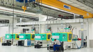
- Production Volume & Equipment: To tailor the mold architecture (single vs. multi-cavity) and ensure compatibility with target machinery for optimal cycle times.
- Material & Tooling Strategy: Selecting premium, heat-treated tool steels (like H13) for core components of the mold, ensuring that they can withstand thermal cycling and maintain precision over their full lifespan.
This phase often includes preliminary digital simulations to identify potential filling or cooling issues upfront, de-risking the project before any steel is cut.
Phase 2 – Design for Manufacturability (DFM) & Structural Optimization
In this phase, the mold is reviewed and optimized for manufacturability (DFM). The goal is to adapt the geometry—where permissible—to guarantee reliable, high-quality production.
- Engineers recommend optimal, uniform wall thickness to promote even filling and solidification, preventing warpage.
- Drafts and fillets are strategically added to ensure clean part ejection and enhance metal flow, extending mold life.
- Features such as very small holes or intricate details are identified as candidates for secondary CNC machining. This practice protects delicate core pins in the mold, reducing maintenance downtime and improving part consistency.
Phase 3 – Strategic Mold Architecture & Parting Line Definition
The placement of the parting line, the seam or line on a finished part where the two halves of the mold come together, is a pivotal decision that impacts part quality, tool cost, and production efficiency.
- The parting surface is selected to minimize flash, simplify ejection, and ensure critical cosmetic or functional faces are formed in a single die half for superior finish.
- The cavity layout and feeding system (gates, runners, overflows) are designed as an integrated whole. This ensures balanced, turbulent-free metal flow to every cavity in multi-cavity molds, guaranteeing consistency from part to part.
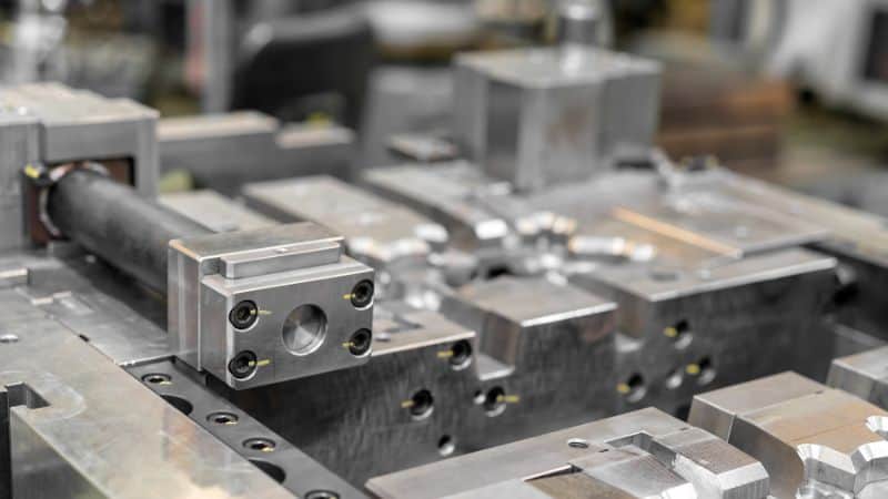
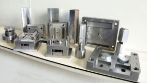
Die Components Overview
An HPDC mold includes several main components:
| Component | Function | Common Material |
|---|---|---|
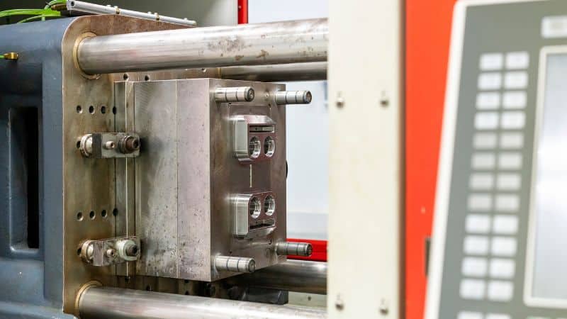
| Cover die | Fixed half of mold; faces injection side | Tool steel (H13) |
| Ejector die | Movable half; ejects casting | Tool steel (H13) |
| Cores and inserts | Form internal cavities or details | Alloy steel |
| Cooling channels | Regulate mold temperature | Copper tubes or drilled holes |
| Ejector pins | Push solidified parts from mold | Hardened steel |
Gating, Runner, and Feeding System Design
Gating System Principles
The gating system controls how molten metal enters the die cavity. It starts at the sprue or biscuit, continues through the runner, and ends at the gate, which connects directly to the cavity. The size, shape, and location of these channels determine how evenly the cavity fills.
Designers often target a laminar flow pattern using streamlined cross-sections and minimal directional changes. The goal is to fill the cavity quickly but without splashing or oxidation.
A well-designed gating system improves casting integrity and cycle time. It keeps pressure consistent throughout the mold, which results in fewer defects and more uniform mechanical properties.
Runner Design Considerations
Runners distribute molten metal from the sprue to the gates. Proper runner layout ensures an even metal supply to all sections of the die. Designers typically choose between tangential and fan runners. Tangential runners guide the flow direction more effectively, while fan runners spread the metal more broadly across a larger gate.
The runner cross-section is usually trapezoidal or semicircular to maintain smooth flow and prevent dead zones. A balanced runner system has equal lengths and cross-sections to make sure each cavity fills at the same rate.
Key design factors include:
- Flow uniformity: Prevents uneven temperatures and solidification.
- Short length: Reduces pressure loss.
- Adequate thickness: Keeps the metal hot enough to reach all gates.
Adjusting runner geometry can also influence metal speed and cooling rate, helping control shrinkage and surface finish quality.
Overflow and Vent Design
Overflows and vents allow gas and excess metal to exit the cavity during filling. Without them, trapped air forms voids, blisters, or incomplete fills. In HPDC, vents usually sit at the farthest points from the gates, where air gathers as the metal advances.
Vents must be large enough to release gas but small enough to stop molten metal leakage. Common vent designs use thin slots that connect to small overflow pockets. These pockets collect impurities and the first metal that enters, which may contain oxides or cold material.
An effective venting system shortens filling time and stabilizes cavity pressure. Engineers often combine vent and overflow design with vacuum systems for high-integrity castings.
Thermal Management and Solidification Control
Cooling Channel Layout
The cooling channel layout defines how heat moves through the die during each casting cycle. Designers use a mix of straight-drilled, conformal, and spot-cooling channels to maintain even temperature profiles. Conformal channels, often made using additive manufacturing, follow the contour of the die cavity and allow more precise heat removal near complex shapes.
Balanced cooling reduces hot spots at gating or thin-wall areas and avoids overcooling in less active zones. Engineers typically analyze thermal gradients using simulation tools to decide the optimal flow rate and channel spacing. Materials with good thermal conductivity, such as copper inserts, can assist in areas requiring faster heat extraction.
Stable die temperature leads to better solidification control, shorter cycle times, and longer die life. A well-designed layout reduces energy use and limits thermal fatigue, improving both productivity and part quality.
Heat Sink Strategies
Heat sinks, both built-in and external, help manage regions that tend to retain too much heat. They draw excess energy away from the die surface through conduction or controlled coolant flow. Common materials include copper alloys or graphite-based composites, chosen for their high thermal conductivity and durability.
Engineers often place heat sinks near thicker casting areas where solidification is slower. Combining them with microspray or localized cooling further stabilizes die temperature. Heat sinks also prevent temperature overshoot that could cause thermal distortion or dimensional variations in the casting.
Solidification Simulation
Simulating solidification patterns helps predict metal flow, shrinkage, and porosity before the die is built. Software tools such as ADSTEFAN or FLOW-3D CAST model how molten alloy fills and cools within the cavity. These simulations reveal where premature solidification, air entrapment, or uneven cooling may occur.
By adjusting gate positions, wall thickness, and cooling flow rates in the digital model, engineers can balance solidification fronts and reduce internal stresses. Predictive modeling allows data-driven decisions that shorten design iteration time and lower scrap rates in production.
Defect Prevention in HPDC Die Design
Porosity Reduction Methods
Besides adequate venting, die temperature control, and balanced gating systems, there are also other methods to reduce porosity.
Metal cleanliness plays a major role. Regular degassing and filtration remove impurities that promote gas entrapment. Die coatings help maintain stable temperatures and prevent localized solidification that traps gas bubbles.
Improving Fluidity
Fluidity defines how easily molten metal flows through the die cavity before solidifying. Poor fluidity causes a variety of casting defects, including misruns, cold shuts, and thin-wall defects. It depends on metal temperature, flow path design, and injection speed.
Selecting the correct alloy composition also influences fluidity. Metals with better casting behavior and low oxidation rates allow for thinner and more precise parts. Monitoring injection parameters through simulation tools helps engineers optimize velocity profiles to ensure complete fill without turbulence.
Minimizing Thermal Fatigue
Thermal fatigue wears down die surfaces through repeated heating and cooling cycles. This causes cracking, erosion, and dimensional variation over time. The most direct prevention method is controlling temperature gradients through efficient cooling channels and uniform heat removal.
High-quality die materials with strong thermal shock resistance extend tool life. Surface treatments such as nitriding or ceramic coatings add protective layers that limit metal-to-die adhesion and thermal damage.
Cooperate with An Quality HPDC Die Designing Company
A successful HPDC project requires seamless integration between the mold design and the production process. A quality die manufacturer should always adopt a comprehensive design process, as these optimizations directly impact part quality, and facilitate efficient cycle times and long-term die durability in a production environment.
If you want to examine in detail about how an experienced mold manufacturer handles the whole process step by step, click here for more about the advanced development & management system of Moldie!


