ゲート射出成形は、プラスチック射出成形における溶融樹脂の流れを形作るうえで重要な役割を果たします。ゲートによって、材料がキャビティにどれだけ効率よく充填されるか、ゲート周辺の強度や表面の仕上がりが決まります。ゲート射出成形への理解を深めることで、品質の向上、廃棄物の削減、生産効率の改善につながります。
このガイドでは、Moldieがゲート射出成形の基礎と、材料や用途に応じたゲートの使い分けについて解説します。基本を学ぶことで、生産工程や製品を最適化する際に、より適切な判断ができるようになります。
ゲート射出成形の基礎
What Is a Gate in Injection Molding?
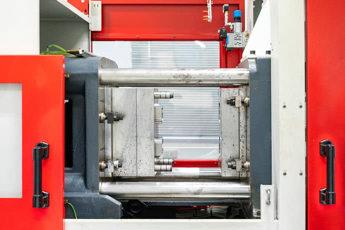
プラスチック射出成形金型の構成要素であるゲートは、ランナーシステムと金型キャビティをつなぐ小さな開口部です。射出成形工程で、溶融樹脂をキャビティ内に流し込みます。ゲートのサイズ、形状、種類によって、材料の充填しやすさや、冷却後のゲートの切り離しやすさが決まります。
一般的なゲートの種類には、エッジゲート、ダイレクト(スプルー)ゲート、ファンゲート、ピンポイントゲート、トンネルゲートなどがあります。それぞれの種類は、部品の形状や生産要件に応じて使い分けられます。適切なサイズのゲートは、樹脂の流れを安定させ、ショートショットや過度な応力などの問題を防ぎます。
Role of Gates in the Injection Molding Process
ゲートは溶融樹脂が金型キャビティに入る流れと、充填・保圧時の圧力の高まりを制御します。ゲートは流量調整器として機能し、速度と温度のバランスを取りながら、材料を均一に行き渡らせます。
ゲートは、冷却、成形サイクル時間、ゲートの切り離しにも影響します。小さなゲートはすばやく冷却され、サイクルを短縮できますが、流れを妨げる場合があります。大きなゲートは充填性を高める一方、目立つゲート跡が残ることがあります。
適切なゲート設計は、成形品のヒケ、ウェルドライン、ボイドなどの不良を抑えます。また、部品全体の密度と寸法精度を均一に保つのにも役立ちます。エンジニアは、材料の粘度や部品の厚み、複雑さに合わせて、ゲートのサイズ、形状、位置を調整します。
Gate Location and Its Impact
ゲート位置によって、樹脂の流れ始める場所と、金型キャビティ内での広がり方が決まります。配置が適切でないと、充填ムラやエアトラップ、外観品質を損なうフローマークが発生することがあります。
厚肉部の近くにゲートを配置すると、収縮を制御し、内部応力を軽減できます。外観が重視される部品では、ゲート跡を目立たなくするため、設計者は見えにくい面にゲートを配置することがよくあります。
ゲートを適切に配置すると、マルチキャビティ金型内で樹脂の流路を均一に保てます。下表は、位置が成形性能に与える影響を示しています。
| Gate Location | Effect on Flow | Impact on Appearance |
|---|---|---|
| Centered | Even filling, low stress | Minimal marks |
| Edge | Faster filling, possible weld lines | Visible marks |
| Hidden (sub-gate) | Clean surface | Marks on angled or hidden surfaces |
射出成形ゲートの種類
Manual Trim Gates
これらのゲートはシンプルで費用対効果に優れていますが、成形後に追加のトリミング工程が必要です。
- Sprue Gate: A large gate directly from the sprue to the part. Best for large, single-cavity molds where appearance isn’t critical. It is simple but leaves a visible mark.
- Edge Gate: Located along the mold’s parting line. It’s a versatile, all-purpose gate used for a wide variety of parts and is easy to machine.
- Tab Gate: Uses a small tab between the runner and part to reduce stress and prevent flow marks. Ideal for flat parts needing a better surface finish.
- Fan Gate: Widens the flow path to spread plastic evenly across a broad area. Excellent for thin, wide parts to prevent warping.
Automatic Gates
これらのゲートは手作業でのトリミングが不要なため効率が高く、大量生産に最適です。
- Tunnel Gate (Submarine Gate): Angled gate that shears off automatically during ejection. It hides the gate mark below the parting line, perfect for small, round parts.
- Pin Gate: A very small, circular gate often used in hot runner systems. It leaves a minimal, clean mark and is common for high-precision cosmetic parts like lenses.
Gates for Specific Flow Needs
樹脂がキャビティに入る流れを制御するため、専用のゲートが必要な部品もあります。
- Diaphragm Gate: Feeds material evenly around a central core, ideal for cylindrical parts to ensure balanced flow and strength.
- Cashew Gate: A curved, tunnel-like gate that feeds plastic from behind the part, completely hiding the gate mark on visible surfaces.
各ゲートの具体的な機能や設計の違いについて詳しくは、射出成形ゲートの種類に関するガイドをご覧ください。
材料と用途がゲート選びに与える影響
Thermoplastics and Material Flow
Different thermoplastics have unique melt viscosities and cooling rates that influence gate selection. Amorphous materials like ABS, PS, and HIPS flow easily and tolerate small gate openings such as pin point or tunnel gates. These gates help maintain a good surface finish and allow automatic separation.
Crystalline plastics like POM or PA need balanced gate sizes for proper packing because of their rapid crystallization and high shrinkage rates. Glass-filled resins require gates designed to minimize excessive shear and fiber breakage, such as tab gates or appropriately sized edge gates.
For transparent materials like PC and PMMA, fan or tunnel gates reduce flow lines and optical defects. PVC and HDPE often use edge or direct gates that provide stable flow and easy trimming. Matching gate type to material flow ensures consistent filling and minimizes stress or warpage.
Part Geometry and Wall Thickness
Part shape and wall thickness determine how melt enters and fills the cavity. Thick-walled parts or large structural components often use direct or edge gates to shorten flow paths and maintain pressure. These gates reduce the risk of short shots and uneven cooling.
Flat parts such as covers or consumer electronics enclosures benefit from fan or tab gates. These distribute material evenly and help maintain a smooth surface. For cylindrical or deep parts, tunnel or pin point gates are preferred because they allow hidden gate placement and clean ejection.
Gate location should promote balanced flow and avoid weld lines. Tool designers often use flow analysis to choose a gate that supports efficient filling and high part quality.
Production Volume and Efficiency
Production scale directly affects gate choice and mold design. High-volume molds often use pin point or tunnel gates for automatic degating, which shortens cycle time and improves production efficiency. These gates support multi-cavity molds and reduce manual labor.
For low-volume runs or prototype tools, edge or direct gates are more cost-effective. They are easier to machine and modify but require manual trimming.
When annual output is high, automated gating systems reduce downtime and wear. Selecting a gate that matches production volume helps balance tooling cost, part quality, and long-term reliability.